System and method for enhanced oil recovery with a once-through steam generator

a steam generator and oil recovery technology, applied in the direction of steam boiler components, fluid removal, insulation, etc., can solve the problems of significantly adversely affecting the performance incomplete separation of oil and water, and lower overall revenue, so as to improve the efficiency of the steam-generating circuit, and eliminate the potential for boiling crises

Active Publication Date: 2011-01-27
PROPAK SYST
View PDF15 Cites 29 Cited by
  • Summary
  • Abstract
  • Description
  • Claims
  • Application Information

AI Technical Summary

Benefits of technology

[0030]In general, the invention provides a system including a OTSG for enhanced oil recovery in which the OTSG is adapted to operate at a much higher exit steam quality, compared to the OTSGs of the prior art operating with high impurity water. The invention eliminates the potential for boiling crises as a result of thinning of a part of the annular water thickness and also substantially eliminates impurity concentration differences within the pipes that can lead to impurity oversaturation and the formation of deposits.

Problems solved by technology

As will be described, the separation of the oil and the water is incomplete, and in addition, many impurities other than oil typically are accumulated in the water.
In the prior art, due to limitations in achieving high steam quality (i.e., greater than 80%), higher steam quantity is required to achieve greater oil flow and revenue which means correspondingly higher energy inputs resulting in lower overall revenue.
Upon such complete vaporization occurring, the impurities precipitate out onto the inner wall surface, forming a deposit which can significantly adversely affect the performance of the steam-generating circuit.
As the steam quality increases in the circuit (i.e., toward the output end), the remaining water film thickness around the inner surface of the pipe decreases, and the potential for dryout increases.
The deposits form a thermal barrier on the inner surface 40 and increase the pipe wall temperature, ultimately leading to lower piping material strength.
In addition, the deposits can reduce the heat transfer and overall amount of produced wet steam flow.
However, as is well known in the art, the radiant chamber may be positioned vertically, rather than horizontally, and a boiling crisis (pipe surface dry out condition) can also occur in a vertical pipe.
However, although a boiling crisis can be avoided using this approach, this approach results in generally lower steam quality.
Such relatively low steam quality means, in effect, that energy inputs into known once-through steam generators are relatively inefficiently utilized.
However, in the SAGD application for enhanced oil recovery, the extent of conditioning typically is very limited, in order to limit costs.
Therefore, in this type of SAGD application, the feedwater typically has relatively high impurities content, i.e., a content that would be unacceptable for most steam generators operating at 100% saturated or superheated outlet steam.
As a result, the annular film of water W is subjected to different rates of evaporation around the perimeter, resulting in a non-uniform concentration of impurities in the remaining water W. This can lead to impurity oversaturation in some regions, resulting in impurities being deposited.
In the horizontal pipe, the non-uniform film thickness (described above) also results in a concentrating of impurities in the thinner part of the film because the thinner film has less diluting effect, compared to the thicker part of the film at the bottom of the pipe.

Method used


Image

  • System and method for enhanced oil recovery with a once-through steam generator
  • System and method for enhanced oil recovery with a once-through steam generator
  • System and method for enhanced oil recovery with a once-through steam generator

Examples


Embodiment Construction

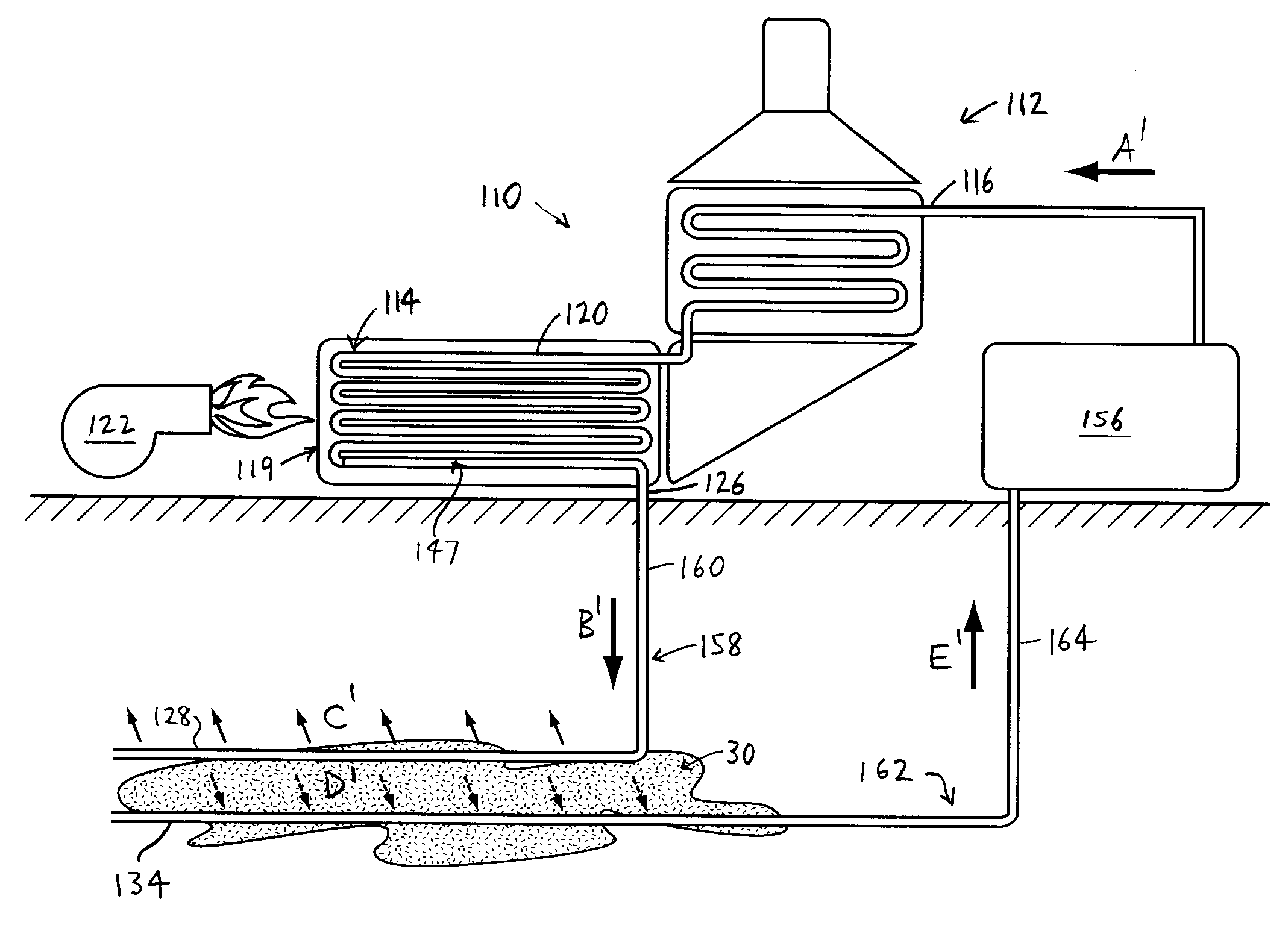
[0050]In the attached drawings, the reference numerals designate corresponding elements throughout. Reference is first made to FIGS. 4-7 to describe an embodiment of a system 112 for extracting crude oil from oil-bearing ground 30. The system 112 preferably includes one or more once-through steam generators 110, each having one or more steam-generating circuits 114 extending between inlet and outlet ends 116, 126, and including one or more pipes 120. Preferably, each steam-generating circuit 114 includes a heating segment 147 thereof positioned to at least partially define a heating portion 119 of the once-through steam generator 110 (FIG. 5A). It is also preferred that the OTSG 110 includes one or more heat sources 122 for generating heat to which the heating segment 147 is subjected. Preferably, the steam-generating circuit 114 is adapted to receive feedwater at the inlet end 116, the feedwater being moved toward the outlet and being subjected to the heat from the heat source to c...


PUM


Abstract

A once-through steam generator including one or more steam-generating circuits extending between inlet and outlet ends thereof and including one or more pipes, the steam-generating circuit having a heating segment at least partially defining a heating portion of the once-through steam generator, and one or more heat sources for generating heat to which the heating segment is subjected. The steam-generating circuit is adapted to receive feedwater at the inlet end, the feedwater being subjected to the heat from the heat source to convert the feedwater into steam and water. The pipe has a bore therein at least partially defined by an inner surface, and at least a portion of the inner surface has ribs at least partially defining a helical flow passage. The helical flow passage guides the water therealong for imparting a swirling motion thereto, to control concentrations of the impurities in the water.

Description

[0001]This application claims the benefit of U.S. Provisional Patent Application No. 61 / 228,809, filed Jul. 27, 2009, and incorporates such provisional application in its entirety by reference.FIELD OF THE INVENTION[0002]The present invention is a system and a method for extracting crude oil from oil-bearing ground.BACKGROUND OF THE INVENTION[0003]Once-through steam generators of the prior art which are used in enhanced oil recovery may include one or more steam-generating circuits at least partially defining a radiant chamber into which heat energy is directed, as is well known in the art. The prior art once-through steam generator may be used for enhanced oil recovery, for example, in a steam-assisted gravity drainage (“SAGD”) application. (Those skilled in the art would be aware of other enhanced oil recovery methods involving the use of steam.) In a SAGD application, as is well known in the art, steam produced by the prior art once-through steam generator is directed into oil-be...

Claims


Application Information

Patent Timeline
Patent Type & Authority Applications(United States)
IPC IPC(8): E21B43/24E21B36/00F22D7/00
CPCE21B36/025E21B43/24E21B43/2406F22B37/103F22B29/06
Inventor BERRUTI, ALEX J.
Owner PROPAK SYST
Why Eureka
Try Eureka