Acoustic Wave Device and Method for Production of Same

a technology of acoustic wave and acoustic resonator, which is applied in the direction of device details, device details, generators/motors, etc., can solve the problems of drop in the reliability of the saw device, and other acoustic wave devices, such as thin film bulk acoustic resonators, encounter problems similar to those described, and achieve high reliability, increase contact area between the substrate and the frame member

Active Publication Date: 2011-01-27
KYOCERA CORP
View PDF8 Cites 65 Cited by
  • Summary
  • Abstract
  • Description
  • Claims
  • Application Information

AI Technical Summary

Benefits of technology

[0014]According to the above acoustic wave device and production methods of the acoustic wave device, the side surface of the columnar electrode is covered by the frame member of the protective cover configuring the inner walls of the vibration space for facilitating vibration of the acoustic wave element, therefore voids which may be formed at the periphery of the columnar electrode can be reduced. Thus breakage of the columnar electrode becomes harder to occur, so a small-sized and highly reliable acoustic wave device can be realized. Further, the frame member extends up to the periphery of the columnar electrode, therefore the contact area between the substrate and the frame member can be increased without enlarging the substrate, and the bonding force between the substrate and the protective cover can be improved. Accordingly, the vibration space can stably keep the tight seal, and a small-sized and highly reliable acoustic wave device can be formed.

Problems solved by technology

As a result, a drop in the reliability of the SAW device is invited because connection failure etc. easily occur when the columnar electrodes 34 break.
As a result, a drop in the reliability of the SAW device is invited.
Above, a SAW device was exemplified as the acoustic wave device, but other acoustic wave devices, for example, thin film bulk acoustic resonators, also encounter problems similar to those described above.

Method used


Image

  • Acoustic Wave Device and Method for Production of Same
  • Acoustic Wave Device and Method for Production of Same
  • Acoustic Wave Device and Method for Production of Same

Examples


Embodiment Construction

[0036]Below, preferred embodiments of the acoustic wave device and the method for production of the acoustic wave device according to the present invention are explained in detail with reference to the drawings. Note that, views used in the following embodiments are schematic views, and dimensional ratios of the figures do not necessarily coincide with the actual ratios. Further, the present invention is not limited to the following embodiments. Various modifications, enhancements, and so on are possible within a range not out of the gist of the present invention.

[0037]SAW Device

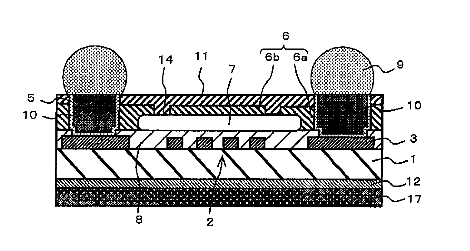
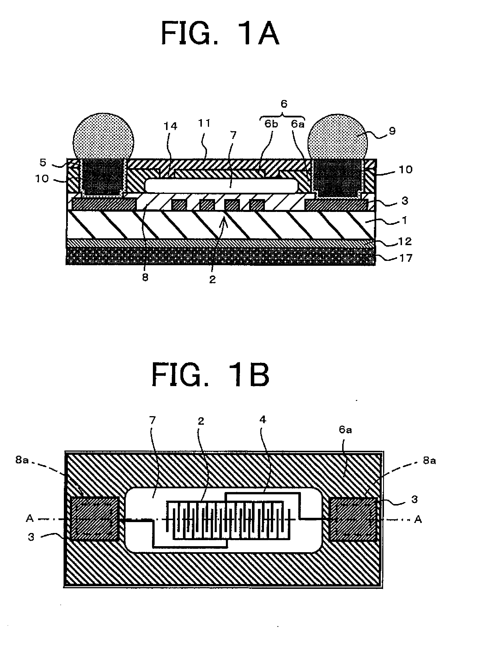
[0038]A SAW device according to the present embodiment is, as shown in FIG. 1A and FIG. 1B, mainly configured by a piezoelectric substrate 1, SAW element 2, connection-use conductors 3, protective cover 6, and columnar electrodes 10. Note that, due to the convenience of illustration, the numbers of comb-shaped electrodes do not coincide between FIG. 1A and FIG. 1B. Note that, FIG. 1B is a view for assisting ...


PUM

PropertyMeasurementUnit
heightsaaaaaaaaaa
thicknessaaaaaaaaaa
thicknessaaaaaaaaaa

Abstract

A small and highly reliable acoustic wave device and a method for production of the same will be provided. The acoustic wave device has a piezoelectric substrate 1; a SAW element 2 on one main surface of the piezoelectric substrate 1; an outside connection-use conductor 3 formed on the one main surface of the piezoelectric substrate 1 and electrically connected to the SAW element 2; a columnar electrode 10 on the outside connection-use conductor 3; and a protective cover 6 defining inner walls of a vibration space 7 for vibration of the SAW element 2 and planarly surrounding a side surface of the columnar electrode 10.

Description

TECHNICAL FIELD[0001]The present invention relates to an acoustic wave device mainly used in a wireless communication circuit of a mobile communication device etc. and a method for production of the same. The acoustic wave device relates to, for example, a surface acoustic wave (hereinafter, sometimes abbreviated as “SAW”) device and a thin film bulk acoustic resonator.BACKGROUND ART[0002]In recent years, portable terminals used for mobile communication have been increasingly reduced in size and lightened in weight. Along with this, the portable terminals are being made multi-banded to be able to handle a plurality of communication systems and are being given more functions. Therefore, the built-in circuits have increased. For this reason, it is strongly demanded that the electronic parts used in the terminals become surface mount parts or small-size parts for improvement of their mounting density.[0003]SAW devices have been known as key parts of portable terminals. A SAW device usu...

Claims


Application Information

Patent Timeline
Patent Type & Authority Applications(United States)
IPC IPC(8): H01L41/04H04R17/00
CPCH03H9/059Y10T29/42H03H9/1092H01L2224/11
Inventor FUKANO, TORUOOKUBO, YOSHIHIRONISHII, JUNYA
Owner KYOCERA CORP
Why Eureka
Try Eureka