Connected Sensor System, Network Unit, And Sensor Unit

a sensor and network technology, applied in the field of connected sensor systems, network units, and sensor units, can solve the problems of difficult wiring, difficult wiring, and difficult operation, and achieve the effect of easy use by users and without complicated wiring

Inactive Publication Date: 2011-01-27
KEYENCE
View PDF5 Cites 16 Cited by
  • Summary
  • Abstract
  • Description
  • Claims
  • Application Information

AI Technical Summary

Benefits of technology

[0030]The present invention provides a connected sensor system which can be easily used by the user and which can give an external input ...

Problems solved by technology

In this kind of sensor system, it is cumbersome to prepare wirings between many sensors and a control apparatus of the sensors.
However, when the user uses the operation switch to perform external input operation, the operation is extremely cumbersome especially in a sensor system including a plurality of connected sensor units.
In addition, there is a problem in that an external input cannot be given to all the sensor units at a time or an external ...

Method used


Image

  • Connected Sensor System, Network Unit, And Sensor Unit
  • Connected Sensor System, Network Unit, And Sensor Unit
  • Connected Sensor System, Network Unit, And Sensor Unit

Examples


Embodiment Construction

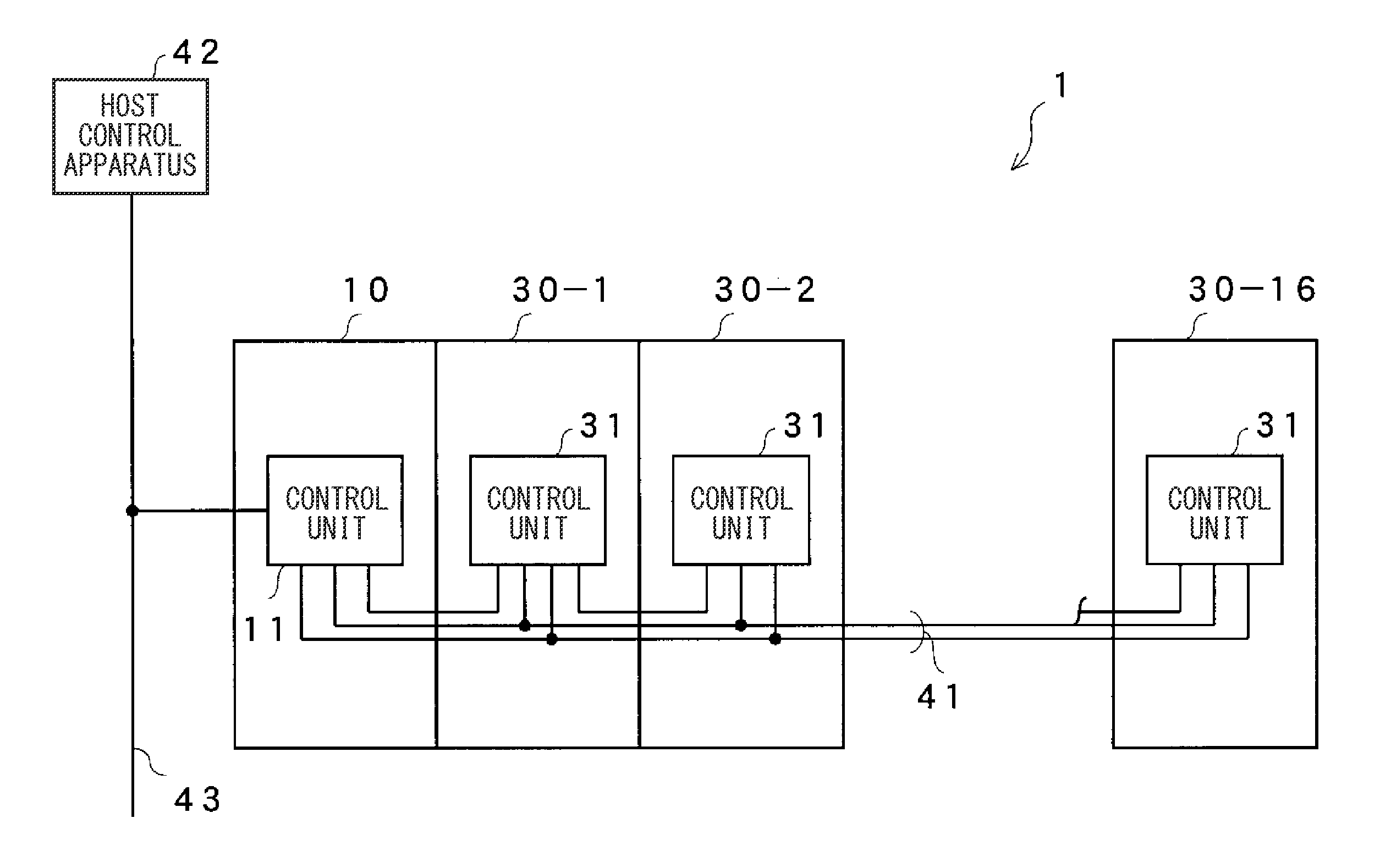
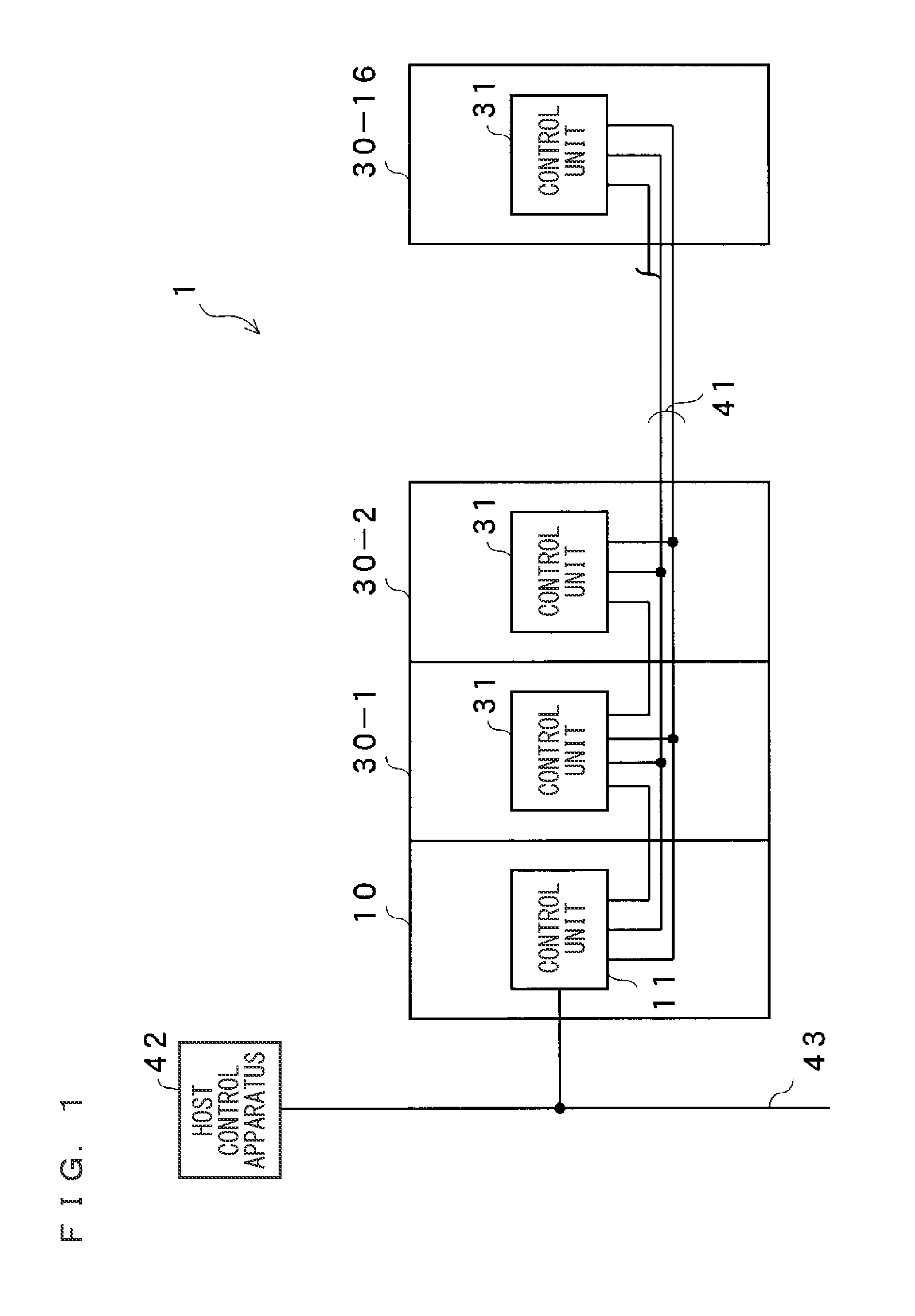
[0044]FIG. 1 is a view illustrating an entire configuration of a connected sensor system according to an embodiment of the present invention. The connected sensor system 1 includes at least one sensor unit connected to a network unit 10. In this embodiment, a series of sixteen sensor units 30-1 to 30-16 are connected to the network unit 10. These units are electrically connected via a serial transmission line 41. The serial transmission line 41 is configured to include at least two lines. Hereinafter, a direction toward the network unit 10 is referred to as upstream direction, and a direction toward the sensor unit 30-16 is referred to as downstream direction. The network unit 10 is configured to collect signals transmitted from the sensor units 30-1 to 30-16, and transmit necessary signal to a host control apparatus 42 such as PLC. The network unit 10 is connected to the host control apparatus 42 via a feed bus 43.

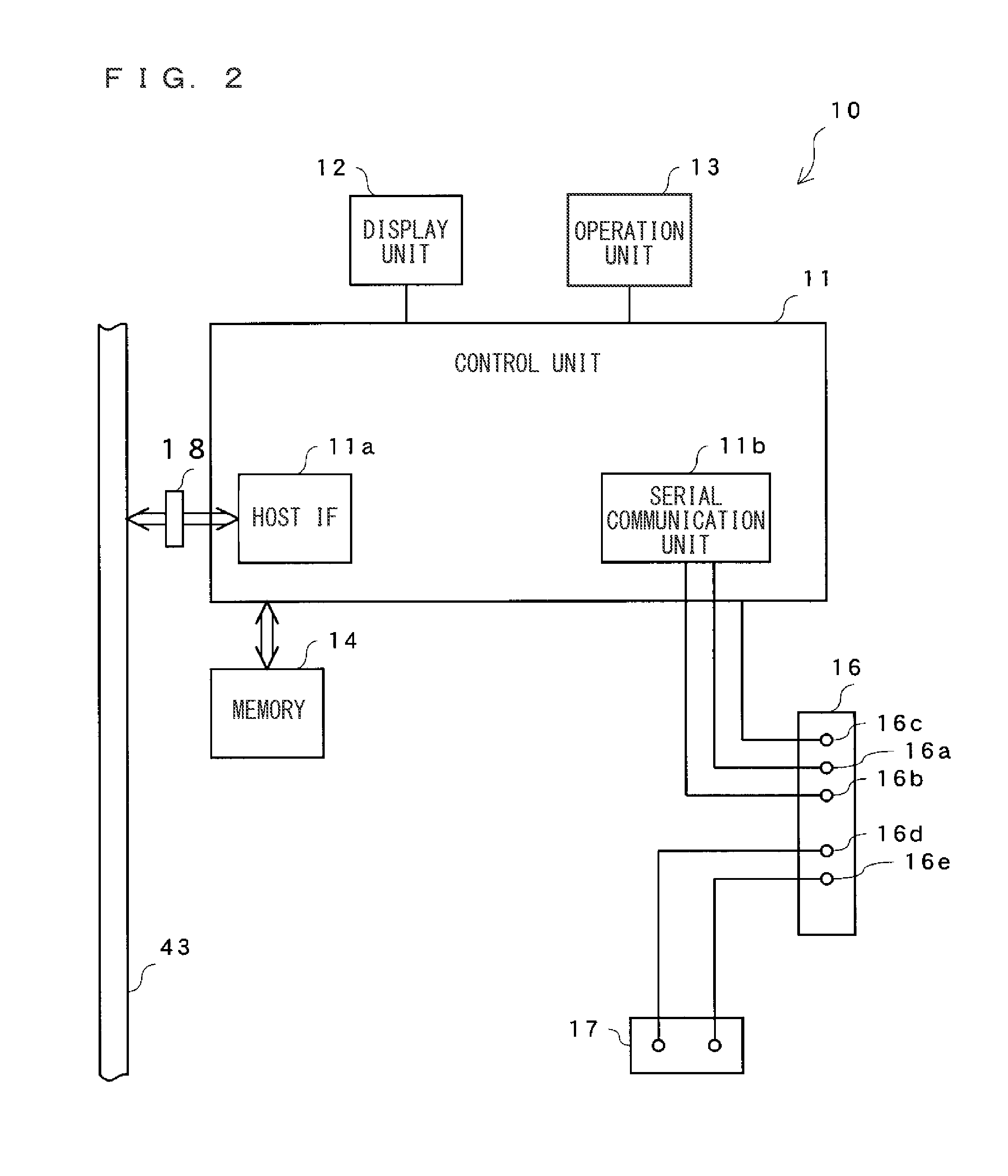
[0045]Subsequently, each unit will be explained in detail. FIG. 2 is...


PUM


Abstract

The present invention provides a connected sensor system which can be easily used by the user and which can give an external input to each sensor unit without making the wiring complicated, and also provides a network unit and a sensor unit used for the connected sensor system. A cyclic communication memory of a network unit is arranged with an external input request region, and an external input signal is stored to a corresponding memory in a host control apparatus. By performing cyclic communication between the network unit and the host control apparatus, the external input signal is stored to the cyclic communication memory of the network unit. Accordingly, the external input signal is transmitted to each sensor unit connected to the network unit, and each sensor unit executes the external input function.

Description

CROSS-REFERENCE TO RELATED APPLICATIONS[0001]The present application claims foreign priority based on Japanese Patent Application No. 2009-173755, filed Jul. 24, 2009, the contents of which is incorporated herein by reference.BACKGROUND OF THE INVENTION[0002]1. Field of the Invention[0003]The present invention relates to a connected sensor system for monitoring a state of an object to be detected, and also relates to a network unit and a sensor unit used for the connected sensor system.[0004]2. Description of the Background Art[0005]In an automated manufacturing line, many sensors for detecting workpieces are arranged in proximity to the workpieces so as to reliably detect the position, the presence / non-presence, the state, and the like of the workpieces.[0006]In this kind of sensor system, it is cumbersome to prepare wirings between many sensors and a control apparatus of the sensors. Therefore, a connected sensor system is utilized, in which these apparatuses are made into units a...

Claims


Application Information

Patent Timeline
IPC IPC(8): H04Q5/22
CPCH04L12/40013
Inventor HANADA, TOMOKIFUKUMURA, KOJI
Owner KEYENCE
Why Eureka
Try Eureka