Fabry-perot interferometer and manufacturing method of the same

a technology of fabry-perot interferometer and manufacturing method, which is applied in the direction of instruments, other domestic objects, optical elements, etc., can solve the problems of difficulty in conventional fabry-perot interferometer

Inactive Publication Date: 2011-01-27
DENSO CORP
View PDF2 Cites 39 Cited by
  • Summary
  • Abstract
  • Description
  • Claims
  • Application Information

AI Technical Summary

Benefits of technology

[0016] According the above Fabry-Perot interferometer, the first mirror and the first electrode are electrically insulated and separated from each other, and / or, the second mirror and the second electrode are electrically insulated and separated from each other. Thus, when the voltage is applied between the first electrode and the second electrode to change the gap, the first mirror and the first electrode does not have the same electric potential, and / or, the second mirror and the second electrode does not have the same electric potential. The electrostatic force is not generated between the first mirror and the second mirror substantially or at all. Therefore, a pull-in limit depends on not the inter-mirror distance "dm" but the inter-electrode-inclusive-portion-distance "de" between the first-electrode-inclusive-portion and the second-electrode-inclusive-portion. Since the inter-mirror distance "dmi" is larger than the inter-electrode-inclusive-portion-distance "dei" in the state of the absence of the voltage application (i.e., dei>dmi), the Fabry-Perot interferometer can change the inter-mirror distance "dm" by more than "dmi.times.1 / 3" from the state of the absence of the voltage application. The Fabry-Perot interferometer can control the inter-mirror distance "de" in a large range without reaching a pull-in limit, and can broaden a spectroscopy band as compared to a convention Fabry-Perot interferometer.

Problems solved by technology

The inventors of the present application have found that a conventional Fabry-Perot interferometer involves a difficulty.

Method used


Image

  • Fabry-perot interferometer and manufacturing method of the same
  • Fabry-perot interferometer and manufacturing method of the same
  • Fabry-perot interferometer and manufacturing method of the same

Examples


first embodiment

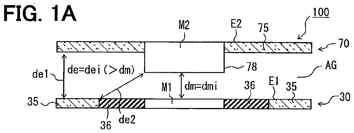
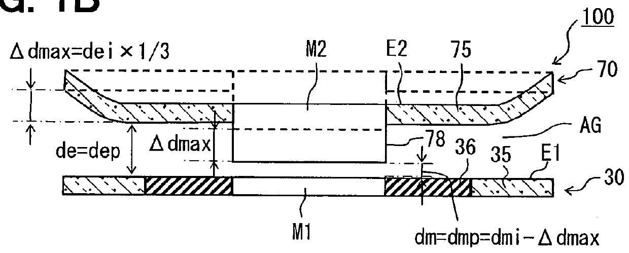
[0041] A first embodiment will be described. FIGS. 1A and 1B are sectional views each illustrating a schematic configuration of a Fabry-Perot interferometer 100 of the first embodiment. More specifically, FIG. 1A illustrates the Fabry-Perot interferometer 100 in an initial state where a voltage application between a first electrode M1 and a second electrode M2 is absent. FIG. 1B illustrates the Fabry-Perot interferometer in a state where a second mirror structure 70 is displaced to the pull-in limit from the initial state. The displacement of the second mirror structure 70 to the pull-in limit may be called herein the maximum displacement .DELTA.dmax. It should be noted in FIGS. 1A and 1B that although the second mirror M2 is illustrated thicker than the first mirror M2, this thickness difference does not define actual thicknesses of the first and second mirrors M1, M2. The thickness difference merely illustrates, for explanatory purpose, that the second mirror M2 is projected towar...

second embodiment

[0087] A Fabry-Perot interferometer 100 of a second embodiment will be described. FIG. 12 is a sectional view illustrating a schematic configuration of the Fabry-Perot interferometer 100 of the second embodiment. FIG. 12 corresponds to FIG. 4.

[0088] A structure difference between the first embodiment and the second embodiment includes the following. In the Fabry-Perot interferometers 100 of the second embodiment, the large refractive index layers 31, 32 of the first mirror M1 are electrically connected with the first electrode 35, and the large refractive index layers 71, 72 of the second mirror M2 are electrically insulated and separated from the second electrode 75. Other structures may be the same between the first and second embodiments.

[0089] As shown in FIG. 12, the first mirror structure 30 is constructed as follows. The first electrode 35 is further disposed at a place where the insulating separation region 36 is formed in the first embodiment. The center region having the f...

third embodiment

[0092] A Fabry-Perot interferometer 100 of a third embodiment will be described. The Fabry-Perot interferometer 100 of the third embodiment and that of the first embodiment can be the substantially same in a basic structure. A different from the first embodiment includes the following. The Fabry-Perot interferometer 100 of the third embodiment is constructed to satisfy, in stead of Relation (5), the following relation:

dei.gtoreq.3.times.(1-.lamda.min / .lamda.max).times.dmi Relation (6)

where ".lamda.min" and ".lamda.max" are respectively a minimum wavelength and a maximum wavelength of a wavelength range of transmitted light. Explanation will be given below on Relation (6). In the initial state of no voltage application, the inter-mirror distance "dm" between the first mirror M1 and the second mirror M2 has the largest value "dmi", and the wavelength of the transmitted light is maximum ".lamda.max". The distance "dmi" and the wavelength ".lamda.max" satisfy

dmi=.lamda.max.times.1 / 2. Re...


PUM


Abstract

A Fabry-Perot interferometer and a manufacturing method of the same are disclosed. The Fabry-Perot interferometer includes a first mirror structure and a second mirror structure opposed to each other with a gap therebetween. A first mirror and a first electrode of the first mirror structure are electrically insulated from each other, or, a second mirror and a second electrode of the second mirror structure are electrically insulated from each other. In a state of voltage application between the first and second electrode, a distance “dmi” between the first mirror and the second mirror is shorter than a distance “dei” between a first-electrode-inclusive-portion and a second-electrode-inclusive-portion.

Description

[0001] The present application is based on Japanese Patent Application No. 2009-170310 filed on Jul. 21, 2009, disclosure of which is incorporated herein by reference.[0002] 1. Field of the Invention[0003] The present invention relates to a Fabry-Perot interferometer including a first mirror structure and a second mirror structure arranged opposed to each other with a gap therebetween. The present invention also relates to a manufacturing method of such Fabry-Perot interferometer.[0004] 2. Description of Related Art[0005] For reduction of size of a Fabry-Perot interferometer, the use of MEMS (micro electro mechanical systems) technology to configure a Fabry-Perot interferometer has been proposed in, for example, Patent Documents 1 and 2.A Fabry-Perot interferometer described in Patent Document 1 includes a pair of mirror structures arranged opposed to each other with an air gap therebetween. In each mirror structure, a silicon dioxide layer (i.e., a small refractive index layer) is ...

Claims


Application Information

Patent Timeline
Patent Type & Authority Applications(United States)
IPC IPC(8): G01B9/02
CPCG02B26/001G01J3/26
Inventor IWAKI, TAKAOWADO, HIROYUKI
Owner DENSO CORP
Why Eureka
Try Eureka