

Watertight rope light
a rope light and watertight technology, applied in the direction of lighting and heating apparatus, semiconductor devices of light sources, lighting support devices, etc., can solve the problems of the head side of the light emitting diodes being illuminated, the whole set of lights goes out of function when one of the lights is dead, and the light emitting diodes are difficult to us
- Summary
- Abstract
- Description
- Claims
- Application Information
AI Technical Summary
Benefits of technology
Problems solved by technology
Method used
Image

Examples
first embodiment
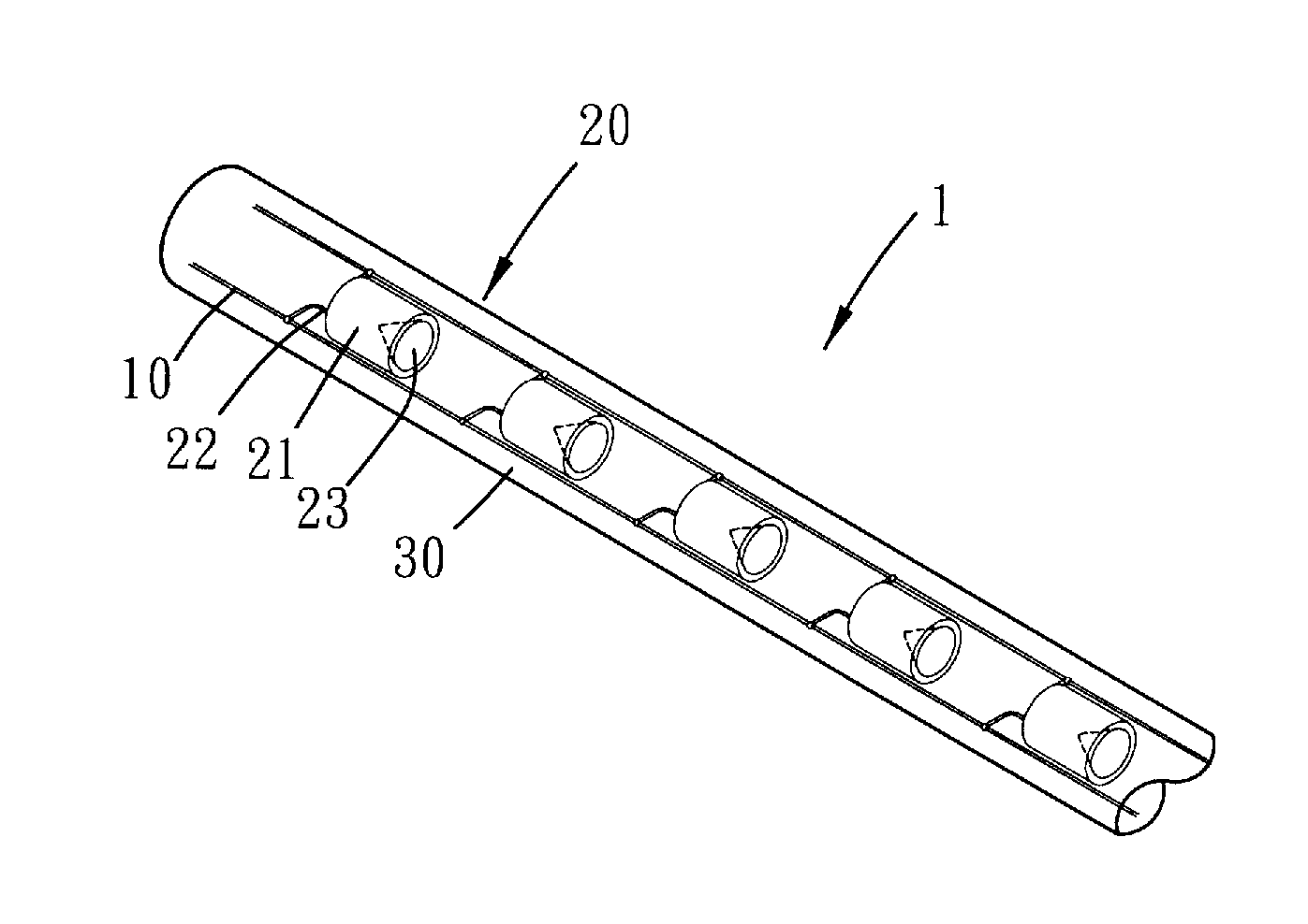
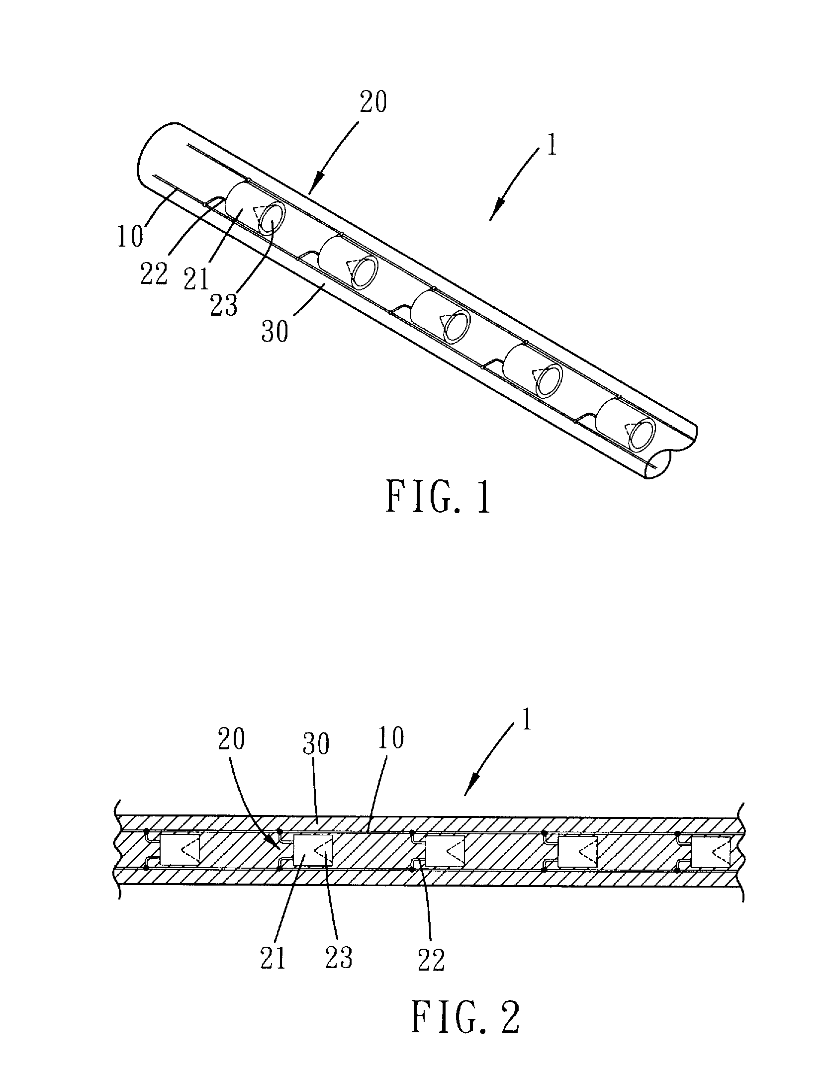
[0019]Please refer to FIG. 1 and FIG. 2 for the present invention. The watertight rope light of the present embodiment is substantially constituted by a single elongated rope light element 1, which includes two parallel wires 10, a plurality of light emitting diodes 20 and a first enclosing layer 30. The wires 10 are made of conducting material such as copper metal. The light emitting diodes 20 are spaced disposed along the wires 10, and an orientation of the light emitting diodes 20 is substantially parallel to the wires 10. Preferably, the light emitting diodes 20 are arranged head-to-heel with each other.
[0020]Each light emitting diode 20 has a semiconductor die (not shown), a lens 21 and two legs 22 including an anode leg and a cathode leg, in which the anode leg connects the semiconductor die with one of the wires, and the cathode leg communicating the semiconductor die with the other wire. In the preset embodiment, the legs 22 joint the wires in a welding manner. The lens 21 e...
second embodiment
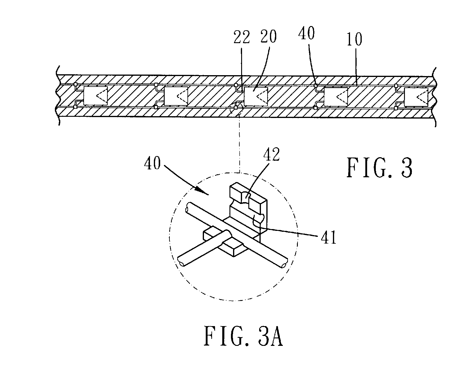
[0022]Please refer to FIG. 3 and FIG. 3A for the present invention. A plurality of adapters 40 are disposed between each leg 22 and its corresponding wire 10 respectively. Each adapter 40 has a wire groove 41 and a leg groove 42. The wire groove 41 has two open ends, and the leg groove 42 has an open end and a connecting end communicating with the wire groove 41. As such, the wire groove 41 is adapted to receive a part of one of the wires 10, and the leg groove 42 is adapted to receive a part of one of the legs 22 so as to electrically connect the leg 22 with the wire 10. It is to be noted that the welding connection between the leg and the wire is sometimes fragile and is easily broken during injection molding process or when the rope light is seriously bent or twisted. On the other hand, such mechanical connecting manner by means of adapters can further ensure the firm electrical connection between the leg and the wire. Or, as shown in FIG. 3B and FIG. 3C, the mechanical connectin...
third embodiment
[0023]Please refer to FIG. 4 and FIG. 5 for the present invention. The rope light in the present embodiment consists of three elongated rope light elements 1. The number of which is variable as a matter of choice. The rope light elements 1 are parallelly arranged and enclosed by a second enclosing layer 50. The second enclosing layer 50 may also be made of PVC material to perform abilities of watertight and flexibility. In addition, the rope light may have light emitting diodes that can emit light of different colors respectively. Furthermore, the light emitting diodes may be arranged in rows or in an alternative manner to provide different visual performance.
[0024]It is to be noted that the legs of a light emitting diode connect with different wires. That is, the light emitting diodes of the present invention is electrically connected with each other in parallel. As a result, the rope light of the present invention can still function even when one or some light emitting diodes go d...
PUM
 Abstract
Description
Claims
Application Information