Receiver and electronic device using the same

Inactive Publication Date: 2011-01-27
PANASONIC CORP
View PDF2 Cites 18 Cited by
  • Summary
  • Abstract
  • Description
  • Claims
  • Application Information

AI Technical Summary

Benefits of technology

[0009]This receiver can demodulate plural received frequency bands simultaneously, thereby reducing the time for channel selection.
[0010]Thi

Problems solved by technology

Conventional receiver 101, however, concurrently uses plural oscillators 102A and 102B in order to concur

Method used


Image

  • Receiver and electronic device using the same
  • Receiver and electronic device using the same
  • Receiver and electronic device using the same

Examples


exemplary embodiment 1

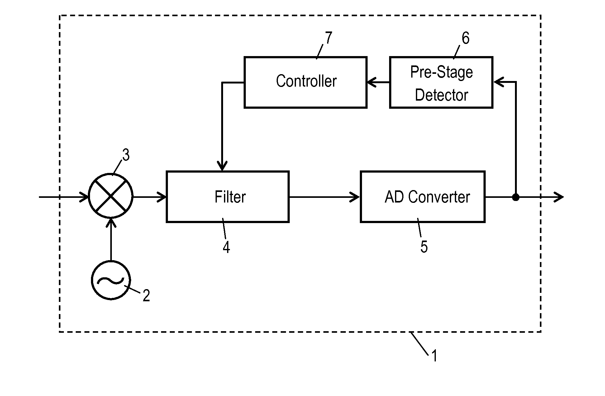
[0045]FIG. 1 is a block diagram of receiver 1 according to Exemplary Embodiment 1 of the present invention. Receiver 1 receives, e.g. terrestrial digital television (TV) broadcasting, and includes oscillator 2, frequency converter 3, filter 4, analog-digital (AD) converter 5, pre-stage detector 6, and controller 7, as shown in FIG. 1. Oscillator 2 generates a local oscillator signal. Frequency converter 3 heterodynes received signals of one or more frequency bands into intermediate frequency (IF) signals, with using the local oscillator signal generated by oscillator 2. Filter 4 is connected to an output of frequency converter 3, and has a cut-off frequency changed. AD converter 5 is connected to an output of filter 4, and converts analog signals of one or more frequency bands into digital signals. Pre-stage detector 6 is connected to an output of AD converter 5, and detects the signal level of the digital signals. Controller 7 controls the cut-off frequency of filter 4 based on the...

exemplary embodiment 2

[0070]FIG. 13 is a block diagram of receiver 13 according to Exemplary Embodiment 2 of the present invention. Receiver 13 receives, e.g. terrestrial digital TV broadcasting and includes oscillator 2, frequency converter 3, filter 4 connected to an output of frequency converter 3, AD converter 5 connected to an output of filter 4, pre-stage detector 6 connected to an output of AD converter 5, and controller 7. Oscillator 2 generates a local oscillator signal. Frequency converter 3 heterodynes the received signals of one or more frequency bands into intermediate frequency (IF) signals with using the local oscillator signal generated by oscillator 2. Filter 4 has a cut-off frequency which can be changed. AD converter 5 converts analog signals of one or more frequency bands into digital signals. Pre-stage detector 6 detects the signal level of the digital signals. Controller 7 controls the cut-off frequency of filter 4 based on the signal level detected by pre-stage detector 6. Receiver...


PUM


Abstract

A receiver includes an oscillator for generating a local oscillator signal, a frequency converter for heterodyning a received signal of one frequency band or a plurality of frequency bands into an intermediate frequency (IF) signals with using the local oscillator signal, a filter connected to an output of the frequency converter and having a cut-off frequency changeable, an analog-digital (AD) converter connected to an output of the filter to convert an analog signal of one frequency band or a plurality of frequency bands into a digital signal, a pre-stage detector connected to an output of the AD converter or connected between the filter and the AD converter to detect a signal level, and a controller for controlling the cut-off frequency of the filter based on the signal level detected by the pre-stage detector.

Description

TECHNICAL FIELD[0001]The present invention relates to a receiver for receiving signals, and an electronic device using the receiver.BACKGROUND ART[0002]FIG. 17 is a block diagram of conventional receiver 101 disclosed in Patent Literature 1. As shown in FIG. 17, receiver 101 includes oscillators 102A and 102B, frequency converter 103, filter 104 connected to an output of frequency converter 103, AD converter 105, band-pass filters 110 and 111 connected to an output of AD converter 105, and demodulators 120 connected to respective outputs of band-pass filters 110 and 111. Oscillators 102A and 102B generate local oscillator signals. Frequency converter 103 heterodynes received signals of one or more channels into intermediate frequency (IF) signals with using the local oscillator signals generated by oscillators 102A and 102B. AD converter 105 converts analog signals received from filter 104 into digital signals.[0003]Conventional receiver 101 can receive signals of plural channels si...

Claims


Application Information

Patent Timeline
IPC IPC(8): H04L27/06
CPCH03H11/126H03H11/1286H03J3/08H03H11/1291
Inventor NAKANO, YUSUKEOZEKI, HIROAKITSUKIO, YASUNOBUFUJII, TAKESHI
Owner PANASONIC CORP
Why Eureka
Try Eureka