
Wireless communication device and communication method of wireless communication device

Inactive Publication Date: 2011-01-27
RENESAS ELECTRONICS CORP
View PDF14 Cites 10 Cited by
  • Summary
  • Abstract
  • Description
  • Claims
  • Application Information

AI Technical Summary

Benefits of technology

[0010]In addition, in order to prevent the disturbance of an image quality caused by discontinuity of data communications of service channels due to the presence of a controlling channel when a streaming service is provided on the service channels, it is necessary to provide a buffer memory with a capacity in accordance with an interrupt time by the controlling channel to secure continuity of data read from a memory, which results in an increased size of an LSI chip and an increased cost of an LSI.
[0012]An object of the present invention is to provide means for eliminating a transmission delay when transmitting emergency information for the sake of relief, security, or the like in a wireless device in conformity with the wireless LAN standard in which if radio waves transmitted from peripheral devices are detected, transmission has to be stopped.
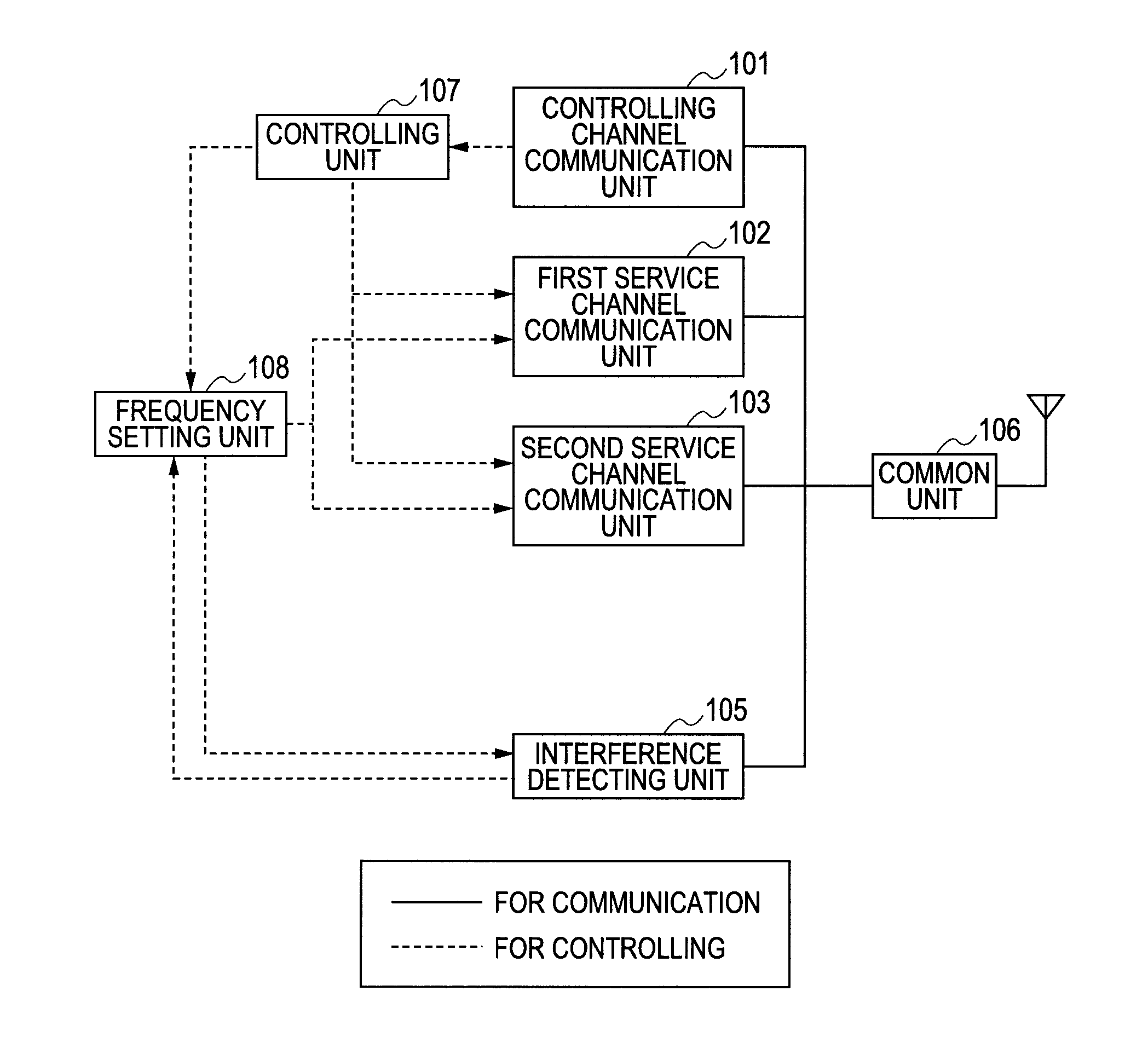
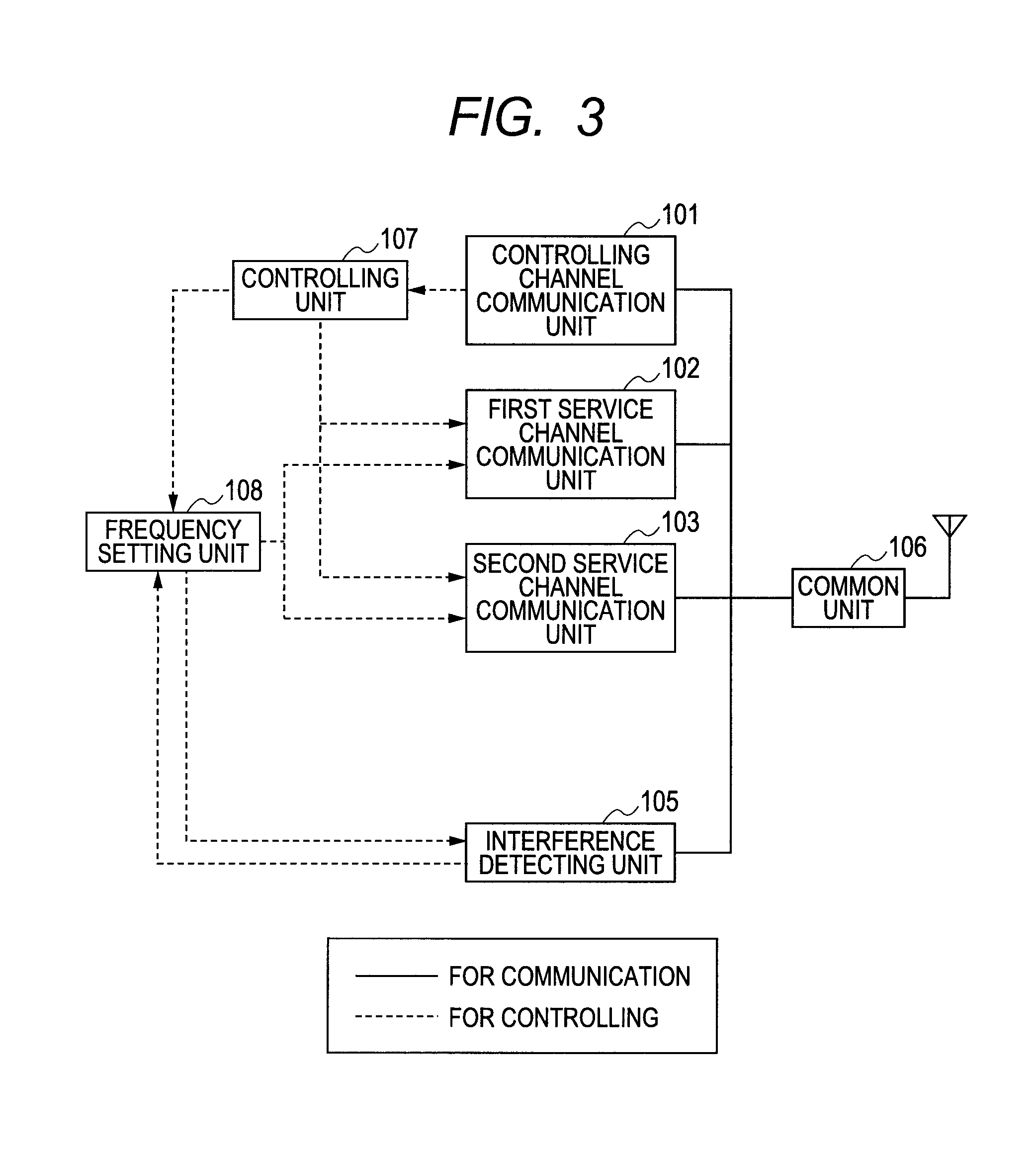
[0015]According to a representative embodiment of the present invention, there is provided a wireless communication device compliant with wireless communication schemes having a controlling channel shared by a plurality of wireless communication terminals linked to base stations, a first high-priority service channel, and a second low-priority service channel, the wireless communication device including: a controlling channel communication unit which performs communications through the controlling channel; a first service channel transmission / reception unit which performs communications through the first service channel; a second service channel transmission / reception unit which performs communications through the second service channel; a controlling unit; a frequency setting unit; and an interference detecting unit, in which the controlling unit; decrypts a frame of the controlling channel received by the controlling channel communication unit; detects a communication priority of the frame if the decrypted frame is a communication request to its terminal; allows the interference detecting unit to detect a usage status of a frequency used on the basis of the communication priority; allows the frequency setting unit to set the operation frequency of the first service channel transmission / reception unit and allows the interference detecting unit to confirm the availability of the channel to be used when the high-priority frame can be coupled; and allows the frequency setting unit to set the operation frequency of the second service channel transmission / reception unit and allows the interference detecting unit to confirm the availability of the channel to be used when the low-priority frame can be coupled.
[0017]According to another representative embodiment of the present invention, there is provided a communication method of a wireless communication device compliant with wireless communication schemes having a controlling channel shared by a plurality of wireless communication terminals linked to base stations, a first high-priority service channel, and a second low-priority service channel, the wireless communication device including: a controlling channel communication unit which performs communications through the controlling channel; a first service channel transmission / reception unit which performs communications through the first service channel; a second service channel transmission / reception unit which performs communications through the second service channel; a controlling unit; a frequency setting unit; and an interference detecting unit, the communication method allowing the controlling unit to perform the steps of: decrypting a frame of the controlling channel received by the controlling channel communication unit; extracting a message type data field from the decrypted frame; selecting and determining any one of the first service channel transmission / reception unit and the second service channel transmission / reception unit for use after obtaining, on the basis of the extracted message type data field, the priority of the service channel coupled by the controlling unit; allowing the interference detecting unit to detect the availability of an expected frequency used by the selected and determined service channel transmission / reception unit; and allowing the frequency setting unit to set the selected and determined service channel transmission / reception unit at the available frequency detected by the interference detecting unit.
[0019]In the multimode wireless communication scheme according to the representative embodiment of the present invention, a plurality of wireless channels are used according to need. Specifically, a wireless channel for communications of large-volume service information is provided separately from a wireless channel for communications of small-volume emergency information. As a result, a line usage rate of the wireless channel for communications of the emergency information can be decreased, thus reducing the provability of occurrence of waiting for transmission according to the wireless LAN standard (IEEE802.11). As a result, when the emergency information is transmitted, it is possible to advantageously eliminate a transmission delay caused by waiting for transmission.

Problems solved by technology

In addition, in order to prevent the disturbance of an image quality caused by discontinuity of data communications of service channels due to the presence of a controlling channel when a streaming service is provided on the service channels, it is necessary to provide a buffer memory with a capacity in accordance with an interrupt time by the controlling channel to secure continuity of data read from a memory, which results in an increased size of an LSI chip and an increased cost of an LSI.
According to the presence of a plurality of devices, radio waves transmitted from the different devices at the same timing supposedly interfere with each other.

Method used


Image

  • Wireless communication device and communication method of wireless communication device
  • Wireless communication device and communication method of wireless communication device
  • Wireless communication device and communication method of wireless communication device

Examples


Embodiment Construction

[0025]Hereinafter, an embodiment of the present invention will be described using the drawings.

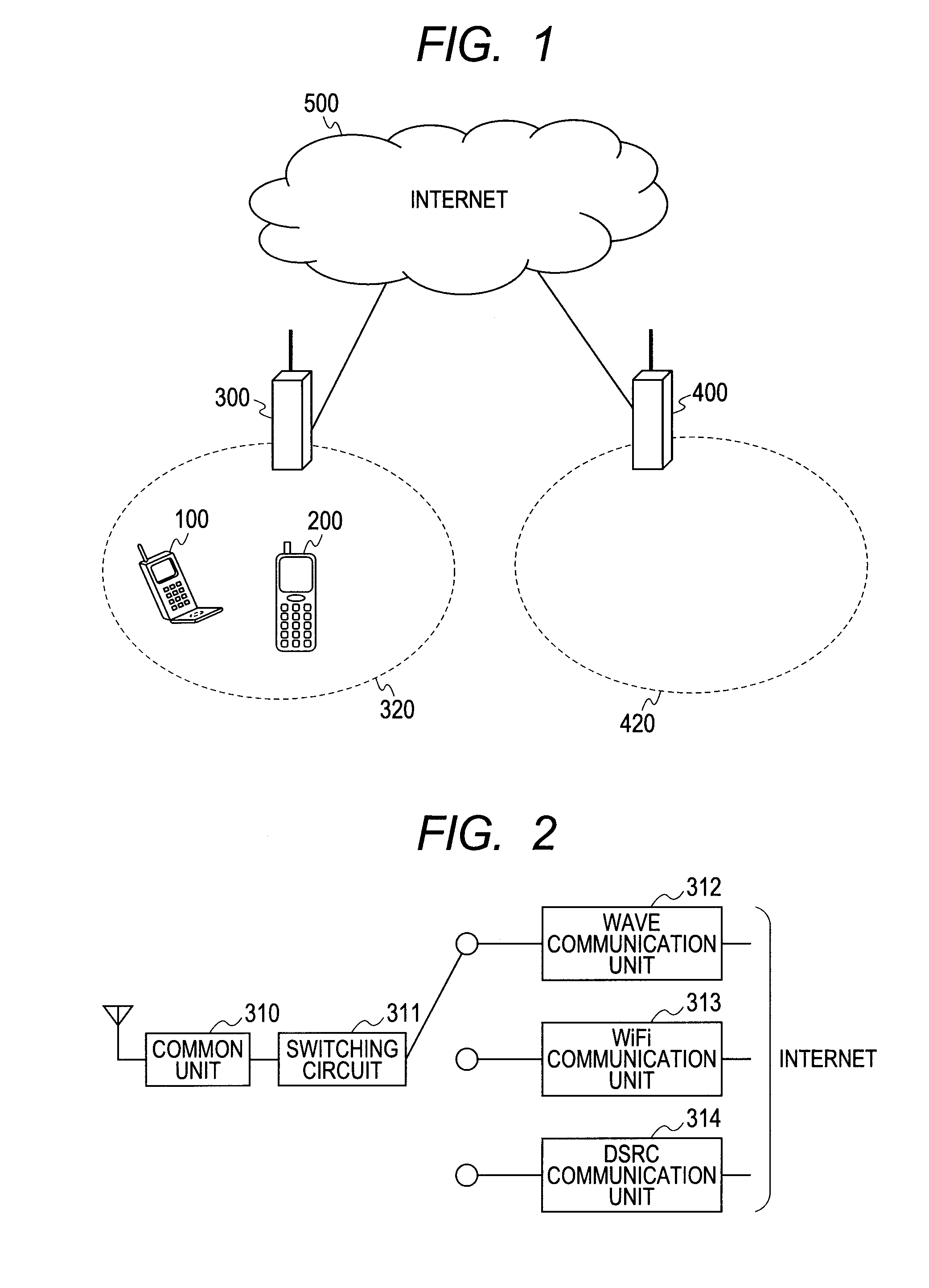
[0026]FIG. 1 is a configuration diagram for showing a system configuration of a multimode wireless communication scheme according to the present invention. FIG. 2 is a configuration diagram for showing a configuration of an access point (base station) used in the multimode wireless communication scheme. Further, FIG. 3 is a configuration diagram of a terminal used in the multimode wireless communication scheme.

[0027]In the multimode wireless communication scheme, an access point 300 and an access point 400 are coupled to each other via the Internet 500. Each of the access points has an access point area in a predetermined range where terminals can be communicated with the corresponding access point. In FIG. 1, the access point 300 has an access point area 320, and the access point 400 has an access point area 420. If terminals 100 and 200 are located in the access point areas, the terminal...


PUM


Abstract

An object of the present invention is to provide means for eliminating a transmission delay when transmitting emergency information for the sake of relief, security, or the like in a wireless device in conformity with the wireless LAN standard in which if radio waves transmitted from peripheral devices are detected, transmission has to be stopped. In a multimode wireless communication scheme having two or more communication schemes, priorities of the communication schemes are set. A high priority or low priority regarding to a message is described in a“message typedata field of a frame of a controlling channel output from the access point side to the terminal side. When the frame of the controlling channel is decrypted on the terminal side, the message type is confirmed, so that the type of a service channel used thereafter is confirmed and the channel is coupled.

Description

CROSS-REFERENCE TO RELATED APPLICATIONS[0001]The disclosure of Japanese Patent Application No. 2009-173877 filed on Jul. 27, 2009 including the specification, drawings and abstract is incorporated herein by reference in its entirety.BACKGROUND OF THE INVENTION[0002]The present invention relates to a scheme of avoiding a transmission delay caused by waiting for transmission of emergency information in an ITS (intelligent transportation system) which supports both of emergency information and various nonemergency service information.[0003]As means for realizing a multimode wireless communication scheme, there is known a cognitive wireless communication. The cognitive wireless communication is a concept of a wireless communication scheme which manages wireless schemes and a usage status of radio waves, changes a parameter used in transmission and reception by a network and a wireless node to avoid interference, and enables efficient communications.[0004]In the cognitive wireless commun...

Claims


Application Information

Patent Timeline
IPC IPC(8): H04B7/00H04W4/90
CPCH04W4/22H04W76/007H04W72/10H04W72/082H04W76/50H04W4/90H04W72/541H04W72/56
Inventor TSUBOI, TSUTOMUYAMADA, IZURUICHIKAWA, HIROKI
Owner RENESAS ELECTRONICS CORP
Learn More