Antenna for behind-the-ear (BTE) devices

a technology of behind-the-ear antennas and antennas, which is applied in the direction of electrical equipment, electrotherapy, artificial respiration, etc., can solve the problems of inefficient and unreliable electrical galvanic connection

Active Publication Date: 2011-01-27
COCHLEAR LIMITED
View PDF11 Cites 64 Cited by
  • Summary
  • Abstract
  • Description
  • Claims
  • Application Information

AI Technical Summary

Benefits of technology

[0011]In a second aspect, there is provided a BTE device for transmitting and/or receiving information via radio frequency, said BTE device comprising: a first antenna element fitted in a body portion of the BTE device; and a second antenna element fitted in an earhook adapted to be attached to the BTE

Problems solved by technology

However, these earhook antennas are often connected to the antenna connector on the BTE device using an

Method used


Image

  • Antenna for behind-the-ear (BTE) devices
  • Antenna for behind-the-ear (BTE) devices
  • Antenna for behind-the-ear (BTE) devices

Examples


Embodiment Construction

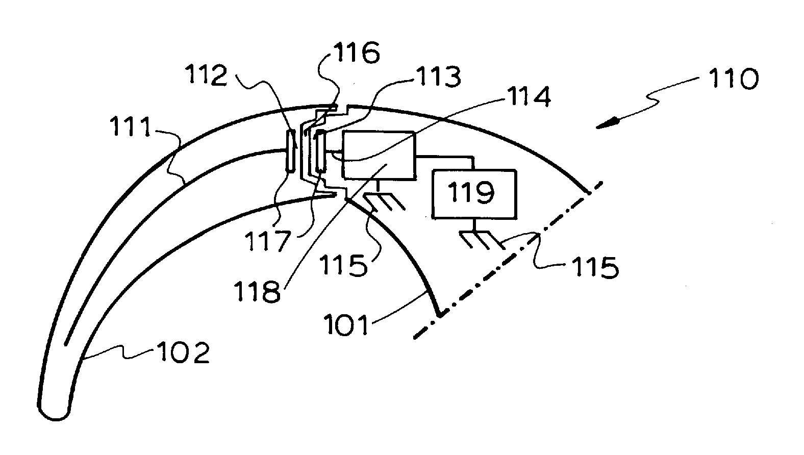
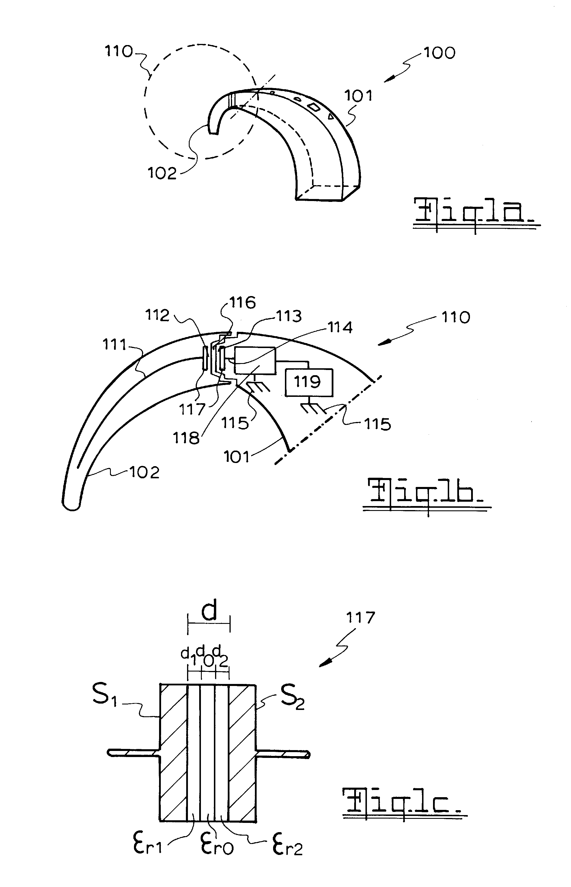
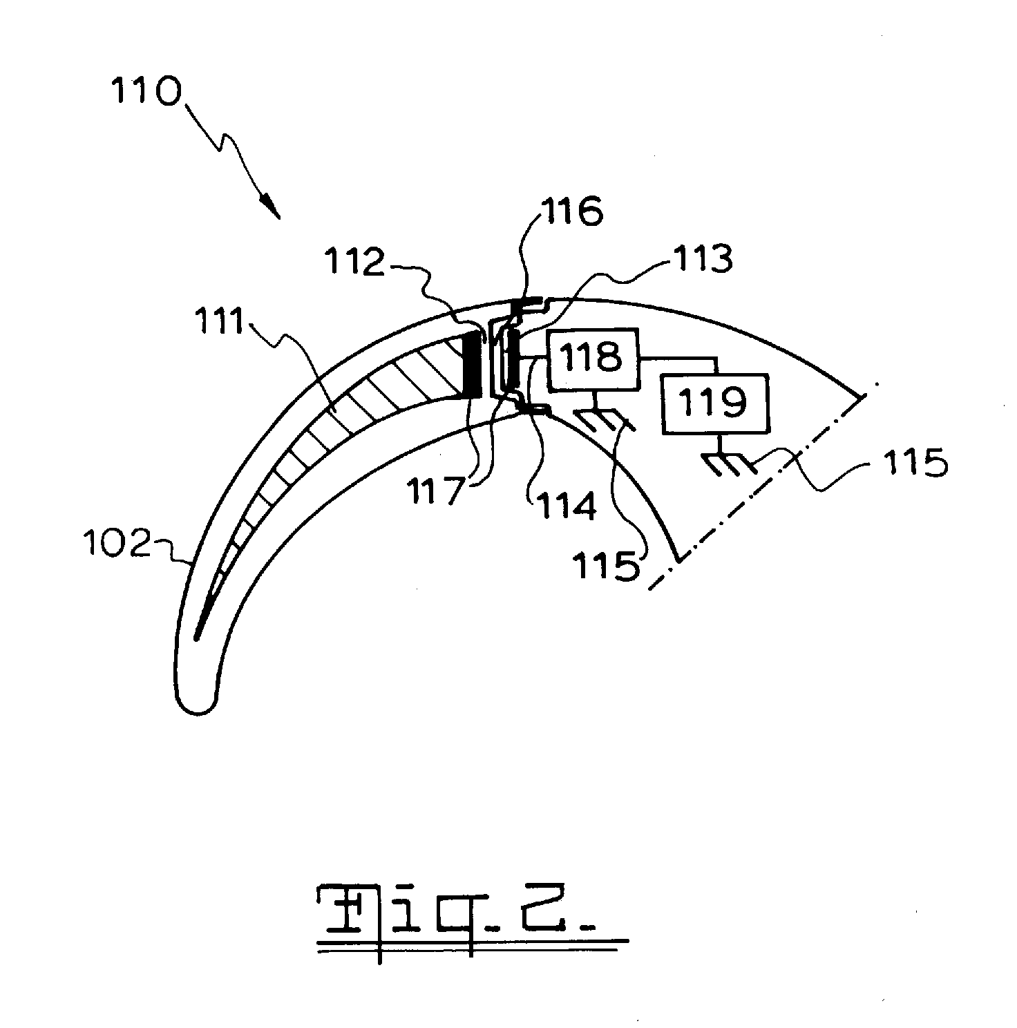
[0022]Aspects of the present invention are generally directed to providing a Behind the Ear (BTE) device with an antenna arrangement that is partly inside the body of the BTE device and partly inside the earhook, with the two antenna elements being electrically coupled by a capacitive connection. In this way, the antenna elements are able to operate as a single antenna.

[0023]As part of the antenna is provided in the earhook as well as in the body of the BTE device, this arrangement allows the body of the BTE device to be reduced in size, while a reliable connection is retained between the two antenna elements using a capacitor based coupling. Such a coupling provides a more efficient and reliable electrical connection than the galvanic connections provided in the prior art, especially in the higher radio frequency ranges, i.e. upwards of about 400 MHz.

[0024]Aspects of the present invention are applicable to a wide variety of BTE devices, and allow an antenna element in the body of a...


PUM


Abstract

An improved antenna device for BTE devices, such a hearing prostheses, is disclosed. Antenna elements (111, 114) are disposed in the BTE body (101) and in the earhook (102), with dielectric material (112, 113) disposed between, so as to form a capacitive coupling.

Description

CROSS-REFERENCE TO RELATED APPLICATION[0001]The present application is a National Stage application of PCT / AU2009 / 000352 entitled “Antenna For Behind-The-Ear (BTE) Devices”, filed on Mar. 26, 2009, which claims priority from Australian Provisional Patent Application No. 2008901474, filed on Mar. 28, 2008, which are hereby incorporated by reference herein.BACKGROUND[0002]1. Field of the Invention[0003]The present invention relates generally to Behind-the-Ear (BTE) devices that wirelessly communicate with implantable hearing aid system prostheses, and more particularly to a radio frequency antenna for a BTE device.[0004]2. Related Art[0005]Implantable hearing prostheses, such as cochlear implants, typically include an internal portion with a receiver and electrical stimulator secured in bone beneath the skin, and an external BTE device with a microphone, speech processor and an antenna.[0006]The antenna is used for communicating processed sound information over a radio frequency link ...

Claims


Application Information

Patent Timeline
IPC IPC(8): A61F11/04H04R25/00A61N1/36
CPCA61N1/37229A61N1/375H04R2225/63H04R2225/51H04R25/606H04R2225/0213
Inventor MESKINS, WERNER
Owner COCHLEAR LIMITED
Why Eureka
Try Eureka