
Exhaust gas treatment device

a gas treatment device and exhaust gas technology, applied in the direction of flanged joints, mechanical equipment, machines/engines, etc., can solve the problems of time and trouble, and the operation efficiency of the cleaning operation is reduced undesired

Active Publication Date: 2011-02-03
NIHON KENKI CO LTD
View PDF5 Cites 44 Cited by
  • Summary
  • Abstract
  • Description
  • Claims
  • Application Information

AI Technical Summary

Benefits of technology

In view of the above-discussed problems with the prior art, it is an object of the present invention to provide an exhaust gas treatment device which is capable of easily mounting and removing the purifying part cylinder incorporating treatment members from the upstream cylinder and the downstream cylinder, thereby making it possible to enhance the operational efficiency in the cleaning operation with respect to the treatment members.
Accordingly, after removing the purifying part cylinder from the upstream cylinder and the downstream cylinder and performing a cleaning operation such as an inspection operation and a repair operation to a treatment member accommodated in the purifying part cylinder, an operation of once again connecting the purifying part cylinder between the upstream cylinder and the downstream cylinder can be quickly and easily performed to enhance an operational efficiency of performing the cleaning operation to the treatment member.
With this construction, in a state where the pin passage hole of the gasket is inserted into the positioning pin disposed in the purifying part cylinder, the gasket is temporarily fixed to the flange portion of the purifying part cylinder by inserting the purifying part cylinder between the upstream cylinder and the downstream cylinder. Therefore, at the time of performing an operation of connecting the purifying part cylinder between the upstream cylinder and the downstream cylinder, the operation of disposing the gasket between the upstream cylinder and the purifying part cylinder and the operation of disposing the gasket between the downstream cylinder and the purifying part cylinder can be simultaneously performed, further increasing an operational efficiency at the time of connecting the purifying part cylinder between the upstream cylinder and the downstream cylinder through the gaskets.
With this construction, when the pin passage hole of the gasket is inserted into the positioning pin of the purifying part cylinder, a peripheral edge portion of the pin passage hole in the gasket latches on the engaging portion of the positioning pin, which can restrict the gasket to move in an axial direction of the positioning pin. Inconsequence, at the time of connecting the purifying part cylinder between the upstream cylinder and the downstream cylinder, an inadvertent disengagement of the gasket from the positioning pin of the purifying part cylinder can be restricted to securely dispose the gaskets between the upstream cylinder, the downstream cylinder and the purifying part cylinder.
(5) Further, according to the present invention, the upstream cylinder and the downstream cylinder are fixed through a support member to the side of the vehicle body. According to this construction, since the upstream cylinder and the downstream cylinder are fixed through the support member to the side of the vehicle body, it is not necessary to fix the purifying part cylinder connected between the upstream cylinder and the downstream cylinder to the side of the vehicle body. In consequence, since only the purifying part cylinder can be removed independently in a state where the upstream cylinder and the downstream cylinder are fixed to the side of the vehicle body, an operational efficiency at the time of performing a cleaning operation to the treatment member accommodated in the purifying part cylinder can be enhanced.

Problems solved by technology

As a result, at the time of performing the cleaning operation, inspection operation, and repair operation, with respect to the DPF, time and trouble are required in the operation of mounting and removing the purifying part cylinder incorporating this DPF with respect to the upstream cylinder and the downstream cylinder.
Therefore, there is a problem in that the operational efficiency in the cleaning operation declines undesirably.

Method used


Image

  • Exhaust gas treatment device
  • Exhaust gas treatment device
  • Exhaust gas treatment device

Examples


Embodiment Construction

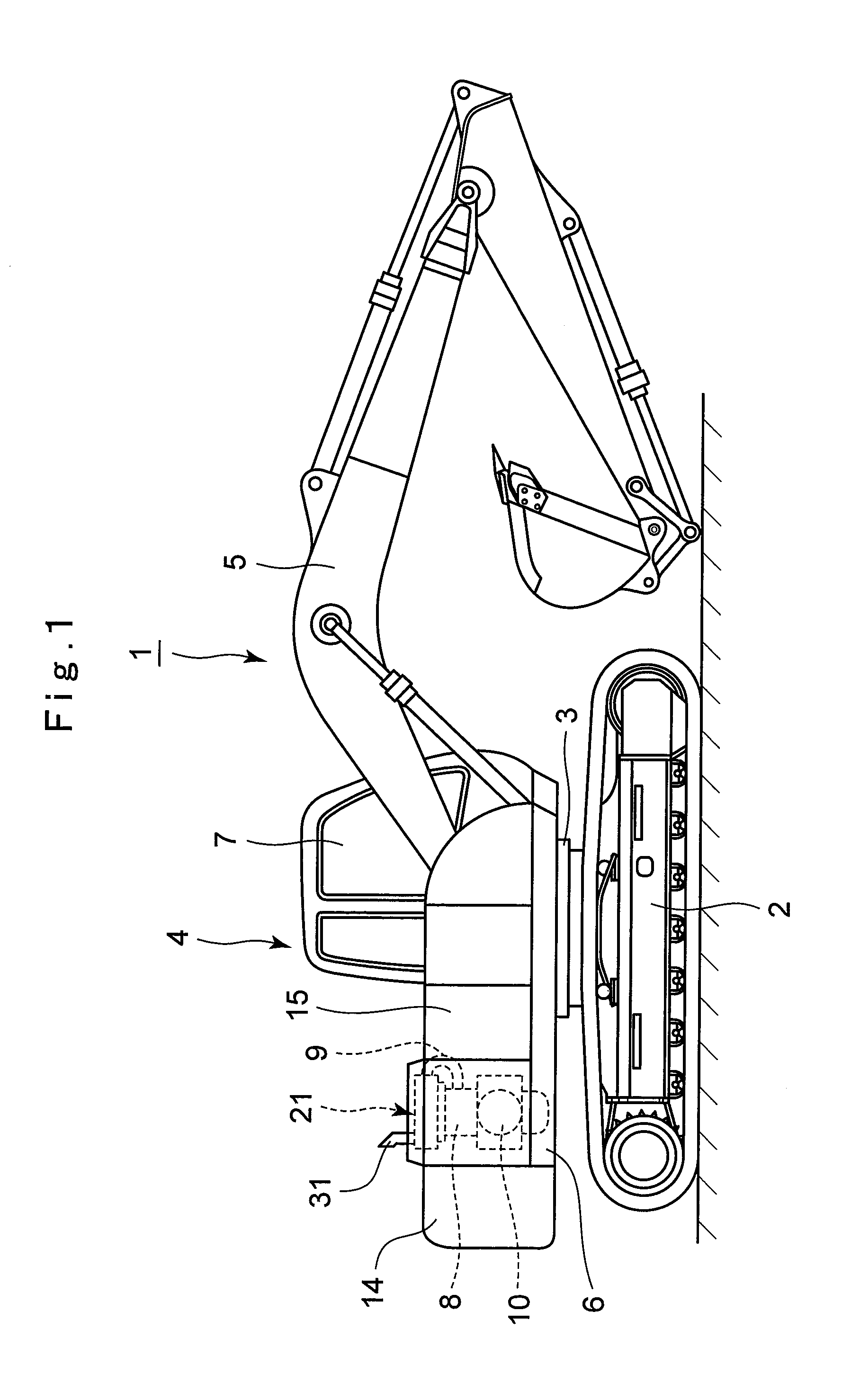
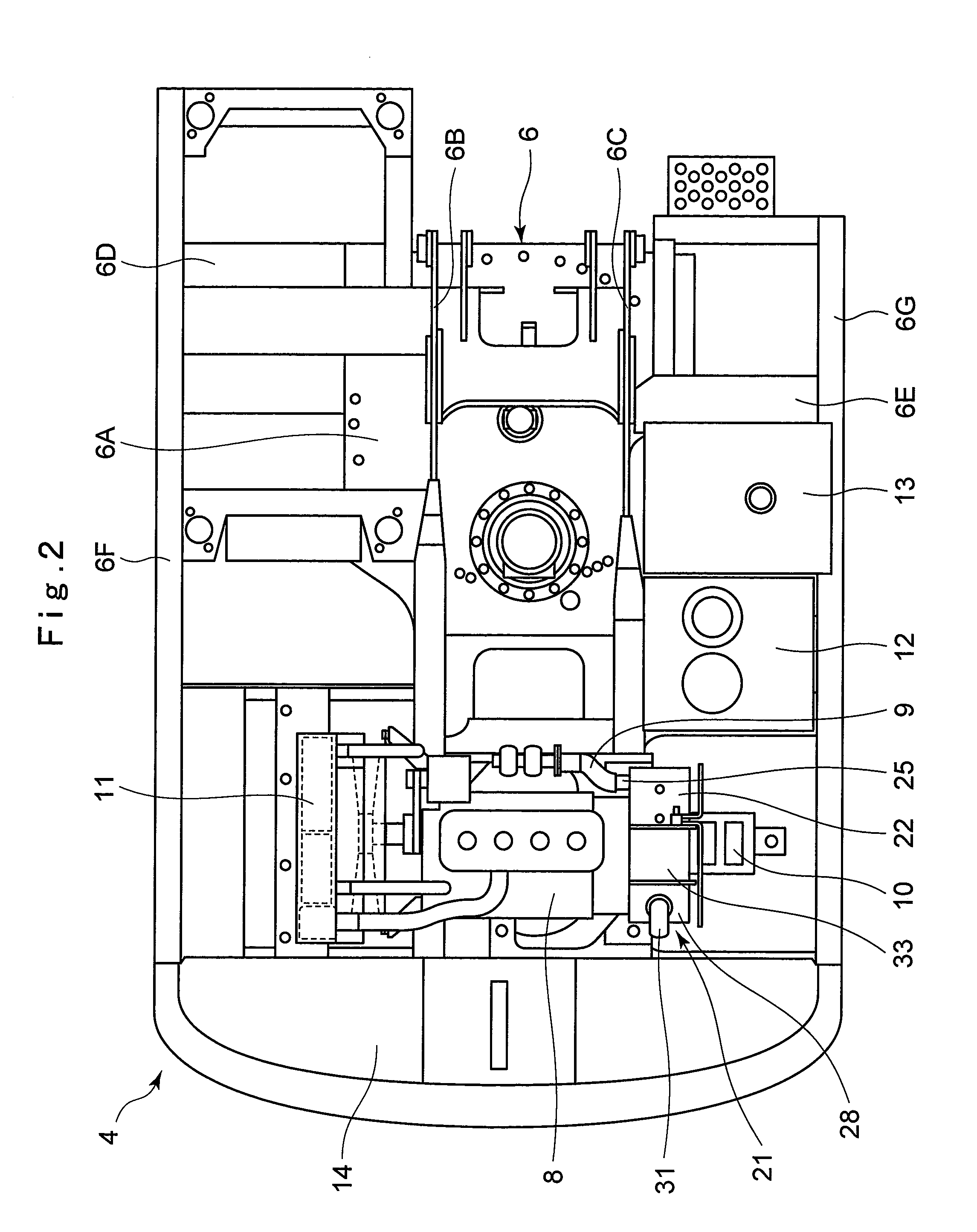
Hereafter, the embodiment of an exhaust gas treatment device in accordance with the present invention is described more particularly with reference to the accompanying drawings, by citing as an example a case in which the exhaust gas treatment device is applied to a hydraulic excavator.

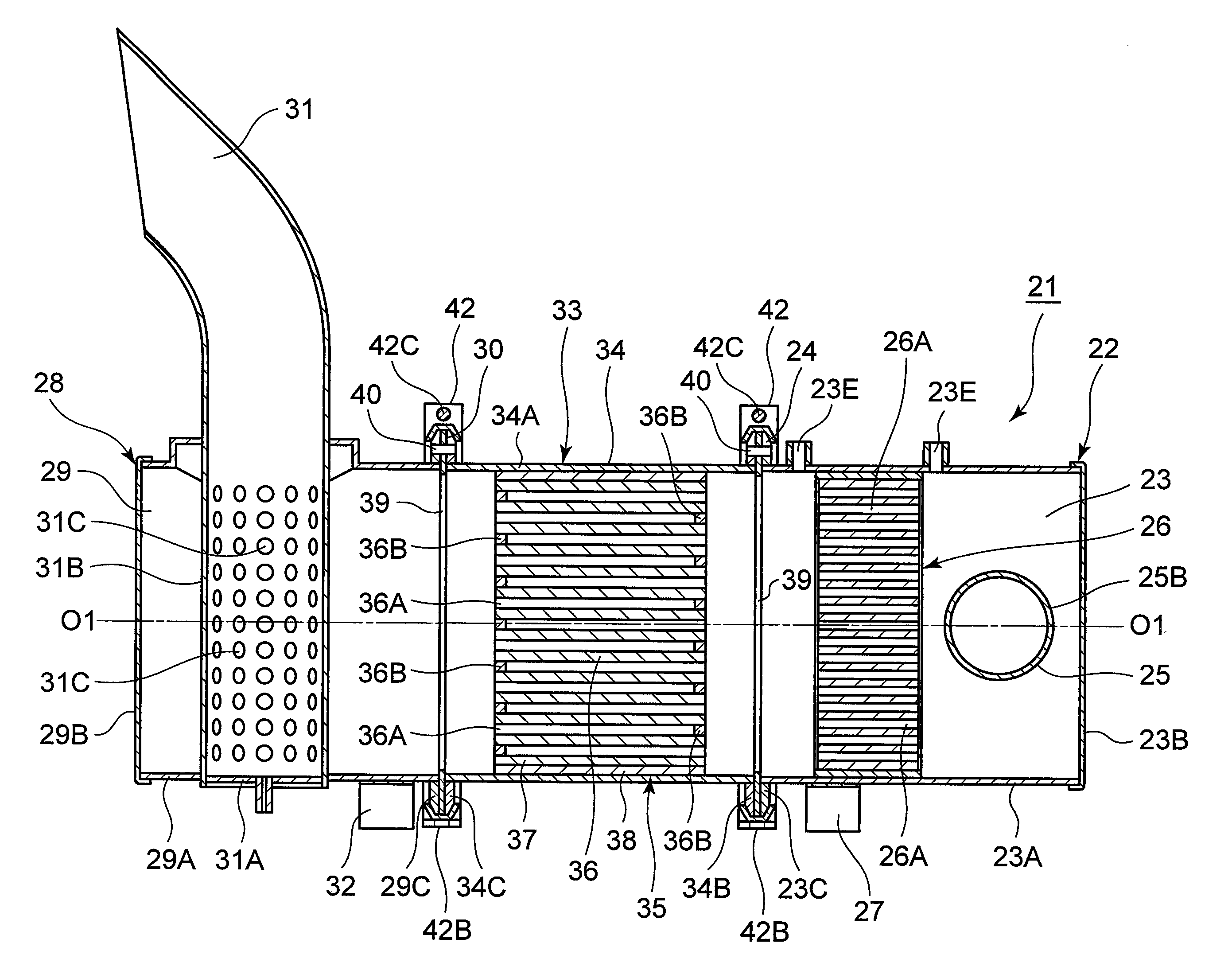
In this embodiment, a particulate matter removing device (PM removing device) for removing particulate matter (PM) emitted from an engine is illustrated as an example of the exhaust gas treatment device.

The exhaust gas treatment device used in this embodiment is constructed such that three cylinders, namely, an upstream cylinder with an oxidation catalyst and a muffler accommodated therein, a downstream cylinder with a muffler accommodated therein, and a filter accommodating cylinder with a DPF accommodated therein, are connected together in series by use of clamping devices each having a V-shape, and are mounted to the engine side by means of support legs.

In the figure, denoted at 1 is a hydraulic ex...


PUM


Abstract

Front and rear side flange portions of a filter accommodating cylinder are provided with positioning pins. A flange portion of an upstream cylinder is provided with a notched groove and a flange portion of a downstream cylinder is provided with a notched groove. In consequence, when the filter accommodating cylinder is connected between the upstream cylinder and the downstream cylinder, each of the positioning pins disposed at the front and rear flange portions is engaged with each notched groove of the upstream cylinder and the downstream cylinder. The filter accommodating cylinder can be positioned to be coaxial with the upstream cylinder and the downstream cylinder. As a result, after performing a cleaning operation to a DPF, an operation of once again connecting the filter accommodating cylinder between the upstream cylinder and the downstream cylinder can be quickly and easily performed.

Description

TECHNICAL FIELDThe present invention relates to an exhaust gas treatment device which is suitably used for reducing exhaust noise of exhaust gas emitted from, for example, an engine, and for removing harmful substances contained in the exhaust gas.BACKGROUND ARTGenerally, a construction machine such as a hydraulic excavator is constituted by an automotive lower traveling structure, an upper revolving structure which is swingably mounted on the lower traveling structure, and a working mechanism liftably mounted on the front side of the upper revolving structure. The upper revolving structure has an engine mounted on the rear side of a revolving frame to drive a hydraulic pump, and has a cab, a fuel tank, an operating oil tank, and the like mounted on the front side of the revolving frame.Generally, a diesel engine is used as the engine of a hydraulic excavator. It is known that the diesel engine emits harmful substances such as a particulate matter (PM) and nitrogen oxides (NOx), and...

Claims


Application Information

Patent Timeline
IPC IPC(8): F01N3/02
CPCF01N3/0335F01N3/035F01N3/106F01N13/1827F01N13/0097F01N2590/08F16L23/032F16L23/08Y02T10/20F01N13/1855F01N13/009F01N13/08F01N13/1805F01N2450/24F01N2450/30Y02T10/12F01N1/02F01N3/02F01N3/24F01N3/28
Inventor SAITO, TOMOYUKIKAMATA, HIROYUKISUGAWARA, HIROKIABE, TOSHIHIROKAMIYA, SHOHEI
Owner NIHON KENKI CO LTD
Features
  • Generate Ideas
  • Intellectual Property
  • Life Sciences
  • Materials
  • Tech Scout
  • Unparalleled Data Quality
  • Higher Quality Content
  • 60% Fewer Hallucinations
Learn More