PCB cutter module with detachable cutters

a technology of pcb cutter module and cutter, which is applied in the direction of metal working apparatus, etc., can solve the problems of accidental injury of the person handling the pcb cutter module, inconvenient use of different pcb cutter modules for cutting, and inability to meet the function of conventional pcb cutter modules, so as to facilitate pc board fabrication and reduce the effect of pc board manufacturing costs

Inactive Publication Date: 2011-02-03
WANG KUO CHUNG
View PDF0 Cites 11 Cited by
  • Summary
  • Abstract
  • Description
  • Claims
  • Application Information

AI Technical Summary

Benefits of technology

[0009]The present invention has been accomplished under the circumstances in view. It is one object of the present invention to provide a PCB cutter module, which allows free arrangement of the cutters to fit different cutting requirements for cutting different designs or different sizes of PC boards. It is another object of the preset invention to provide a PCB cutter module, which allows quick replacement of any damaged cutter individually during PCB fabrication. It is still another object of the present invention to provide a PCB cutter module, which storage of the cutters separately, avoiding accidental injury. It is still another object of the present invention to provide a PCB cutter module, which facilitates PC board fabrication and effectively reduces PC board manufacturing costs.

Problems solved by technology

Conventional PCB cutter modules are not satisfactory in function because of the following drawbacks:1. A conventional PCB cutter module generally comprises a mold plate and a plurality of cutters affixed to the mold plate.
However, it is not economic to use different PCB cutter modules for cutting different board members for making PC boards of different sizes and specifications.3. When a PCB cutter module is not used, the cutters are kept affixed to the mold plate.
During delivering or storing of the PCB cutter module, the person handling the PCB cutter module may be injured by the cutters accidentally, or external objects may be scratched or cut by the cutters accidentally.

Method used


Image

  • PCB cutter module with detachable cutters
  • PCB cutter module with detachable cutters
  • PCB cutter module with detachable cutters

Examples


Embodiment Construction

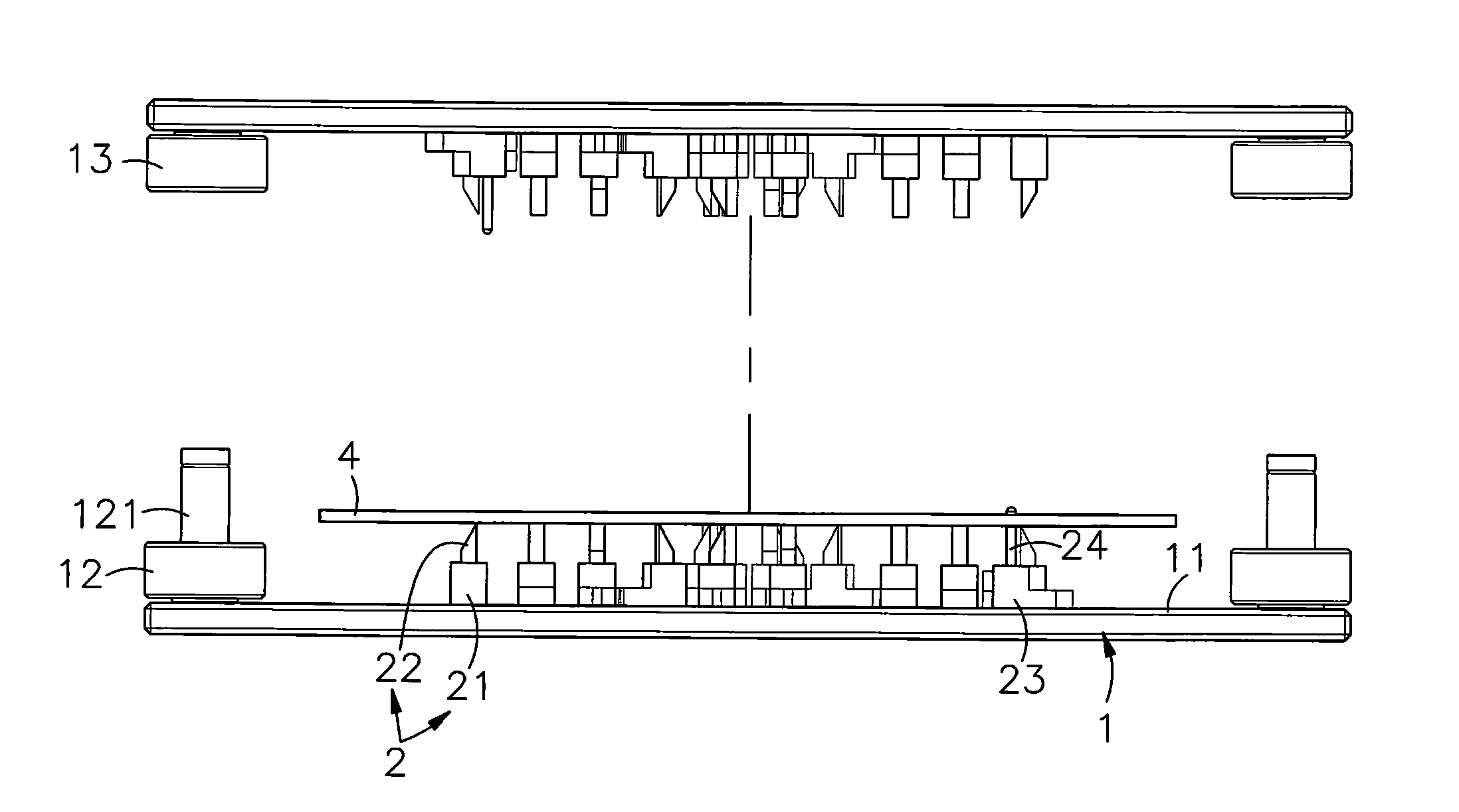
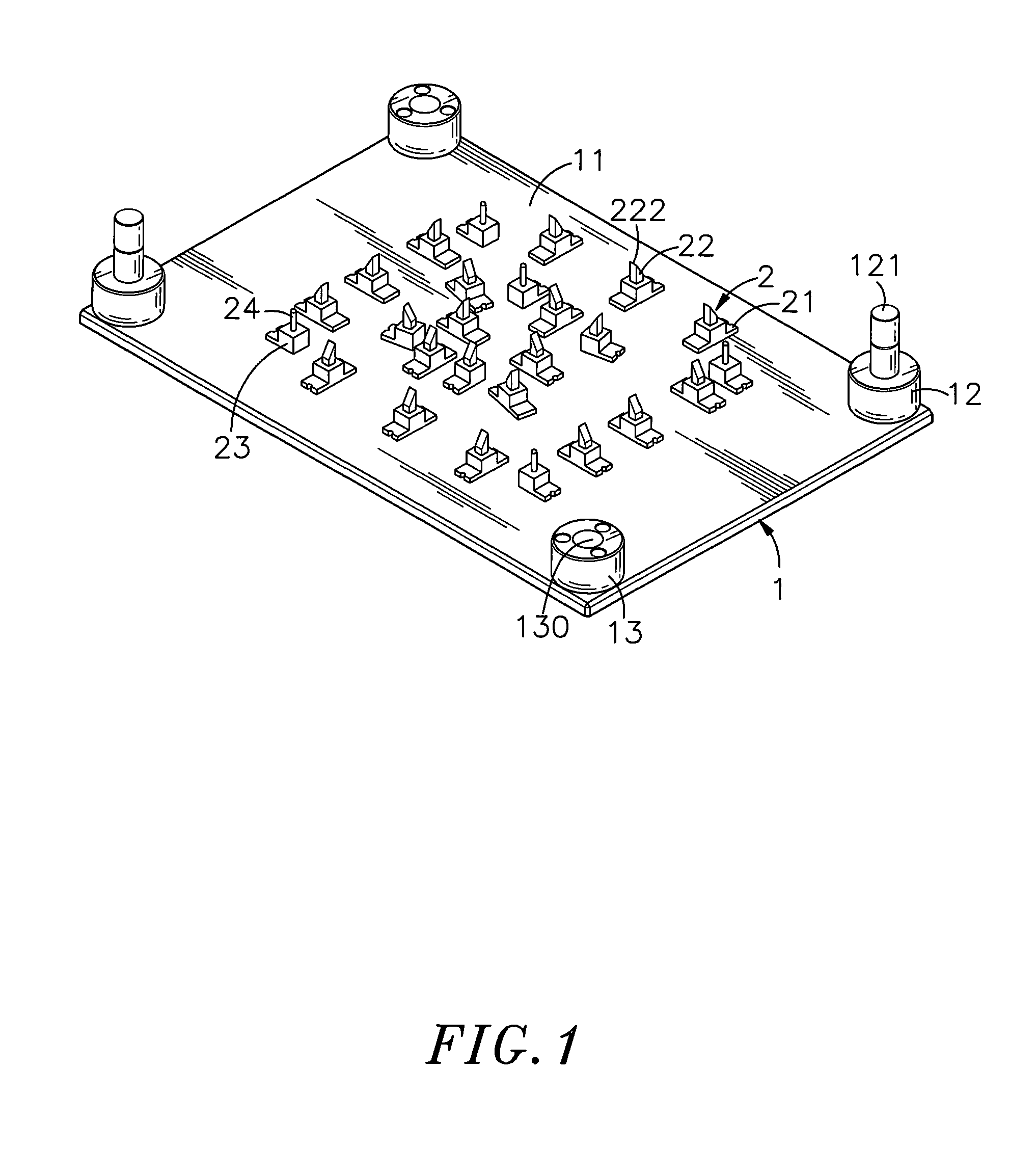
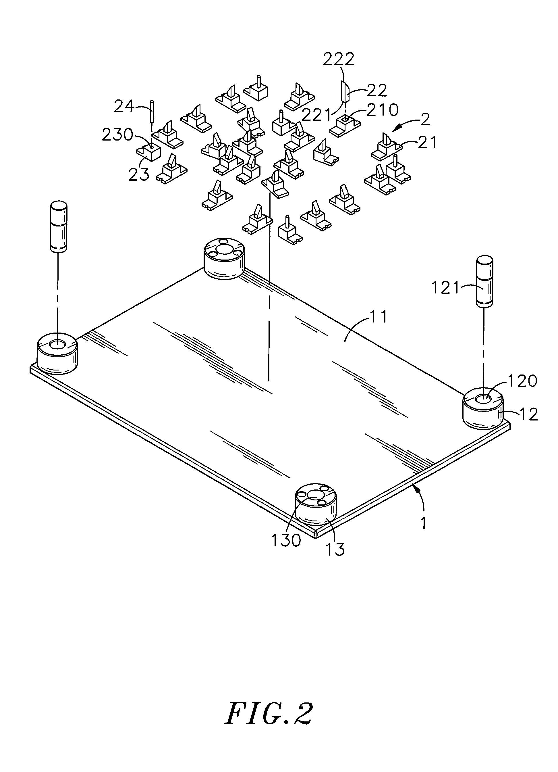
[0021]Referring to FIGS. 1˜3, a PCB cutter module in accordance with a first embodiment of the present invention is shown comprising a base 1 and a plurality of cutters 2.

[0022]The base 1 has a magnetically attractive worktable 11 provided at the top side thereof. The worktable 11 has a plurality of positioning portions 12 and alignment portions 13 alternatively arranged around the border. Each positioning portion 12 defines therein a positioning hole 120 for the mounting of a respective positioning rod 121. Each alignment portion 13 defines therein an alignment hole 130.

[0023]Each cutter 2 comprises a -shaped or L-shaped holder block 21 that has a locating hole 210 formed in the top thereof, and a cutter element 22 that has a base portion 221 fastened to the locating hole 210 of the holder block 21 and a cutting edge 222 disposed at the top side. After installation of the respective cutter elements 22 in the respective holder blocks 21, the cutting edges 222 of the cutter elements ...


PUM

PropertyMeasurementUnit
magnetically attractiveaaaaaaaaaa
magnetic attractionaaaaaaaaaa
attractiveaaaaaaaaaa

Abstract

A PCB cutter module is disclosed to include a base having a magnetically attractive worktable, a plurality of cutters detachably attached to the worktable and secured thereto by magnetic attraction at selected locations in selected directions subject to the design of the PC board to be cut. By means of magnetic attraction, the cutters are adjustably replaceably secured to the magnetically attractive worktable to fit different cutting requirements for cutting different designs of PC boards or different sizes of PC boards.

Description

BACKGROUND OF THE INVENTION[0001]1. Field of the Invention[0002]The present invention relates to PCB cutter modules for cutting PC boards or the like, and more particularly, to such a PCB cutter module, which allows quick adjustment of the positions of cutters to fit different cutting requirements for cutting different designs or different sizes of PC boards.[0003]2. Description of the Related Art[0004]To eliminate the drawbacks of long operation time, complicated processing procedures and low yield rate of conventional manual fabrication methods, many different automatic and semi-automatic machine tools are created. The use of automatic or semi-automatic machine tools greatly reduces the processing time and labor and greatly improves the processing efficiency and quality. Further, the use of automatic or semi-automatic machine tools facilitates mass production of products. Further, different tools may be used for processing substrates for PC boards subject to desired sizes, shapes ...

Claims


Application Information

Patent Timeline
Patent Type & Authority Applications(United States)
IPC IPC(8): B26D7/26
CPCB26D1/09B26D7/2614B26F2210/06B26D2007/2607B26F1/40B26D2001/0033Y10T83/9459
Inventor WANG, KUO-CHUNG
Owner WANG KUO CHUNG
Why Eureka
Try Eureka