Completion system for subsurface equipment

a technology of subsurface equipment and completion system, which is applied in the direction of drilling pipes, wellbore/well accessories, insulation, etc., can solve the problems of inability to achieve high flow rate wells, and the assignment of fluids in each annular fluid channel is typically fixed, so as to achieve efficient management of fluid flows

Active Publication Date: 2011-02-03
GREENFIRE ENERGY
View PDF33 Cites 6 Cited by
  • Summary
  • Abstract
  • Description
  • Claims
  • Application Information

AI Technical Summary

Benefits of technology

[0008]A concentric tubing well completion system and subsurface annular flow crossover are provided. The well completion system creates at least three concentric annular flow channels in a wellbore. One or more subsurface flow crossovers provide for switching fluid flow between the annular flow channels within the completed well. A crossover can be used in conjunction with other subsurface equipment to more efficiently manage fluid flows in the completed well for the purposes of produced fluid extraction and supply of a working fluid to a subsurface device.
[0012]In another aspect of the invention, the system can be assembled into different sections in which the fluid flowing in one annulus may be switched to flow into a different annulus. This can allow changing the flow path of hot and cold fluid streams. The system can be used to recover heat from a fluid stream, control solids precipitation by maintaining fluid temperature, use a heated circulating fluid to lower the fluid viscosity of a produced fluid.

Problems solved by technology

This method is useful for shallow wells having low flow rates but is impractical for wells having higher flow rates or deep wells where pressure drops caused by the required narrow tubing strings are unacceptable.
One problem associated with concentric tubing strings is that the assignment of the fluids in each annular fluid channel is typically fixed.
This may cause a problem, for example, when a subsurface device, such as turbine driven pump, needs to be placed in the wellbore and fluid needs to routed to the device around another intervening device in the tubing string.

Method used


Image

  • Completion system for subsurface equipment
  • Completion system for subsurface equipment
  • Completion system for subsurface equipment

Examples


Embodiment Construction

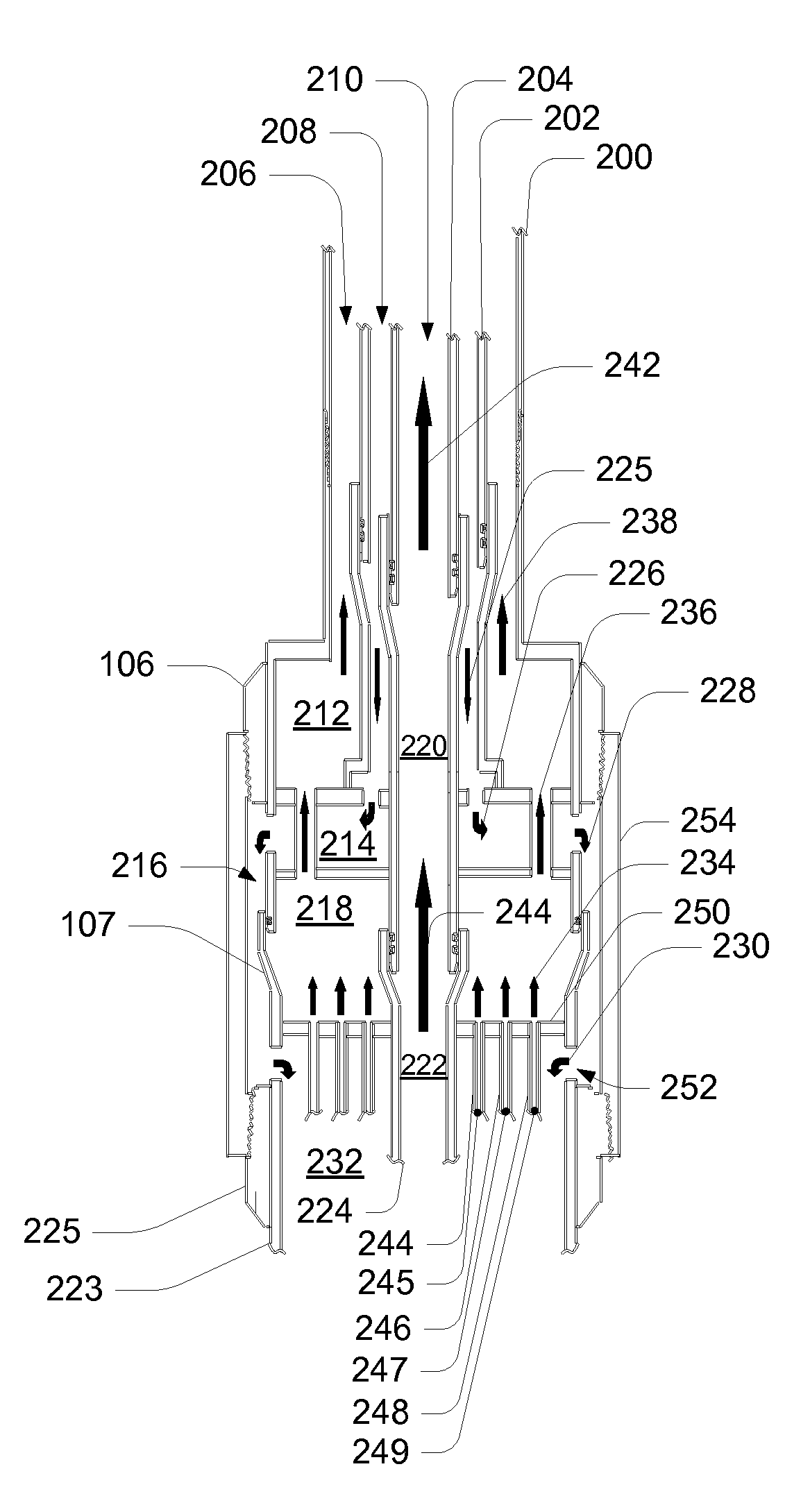
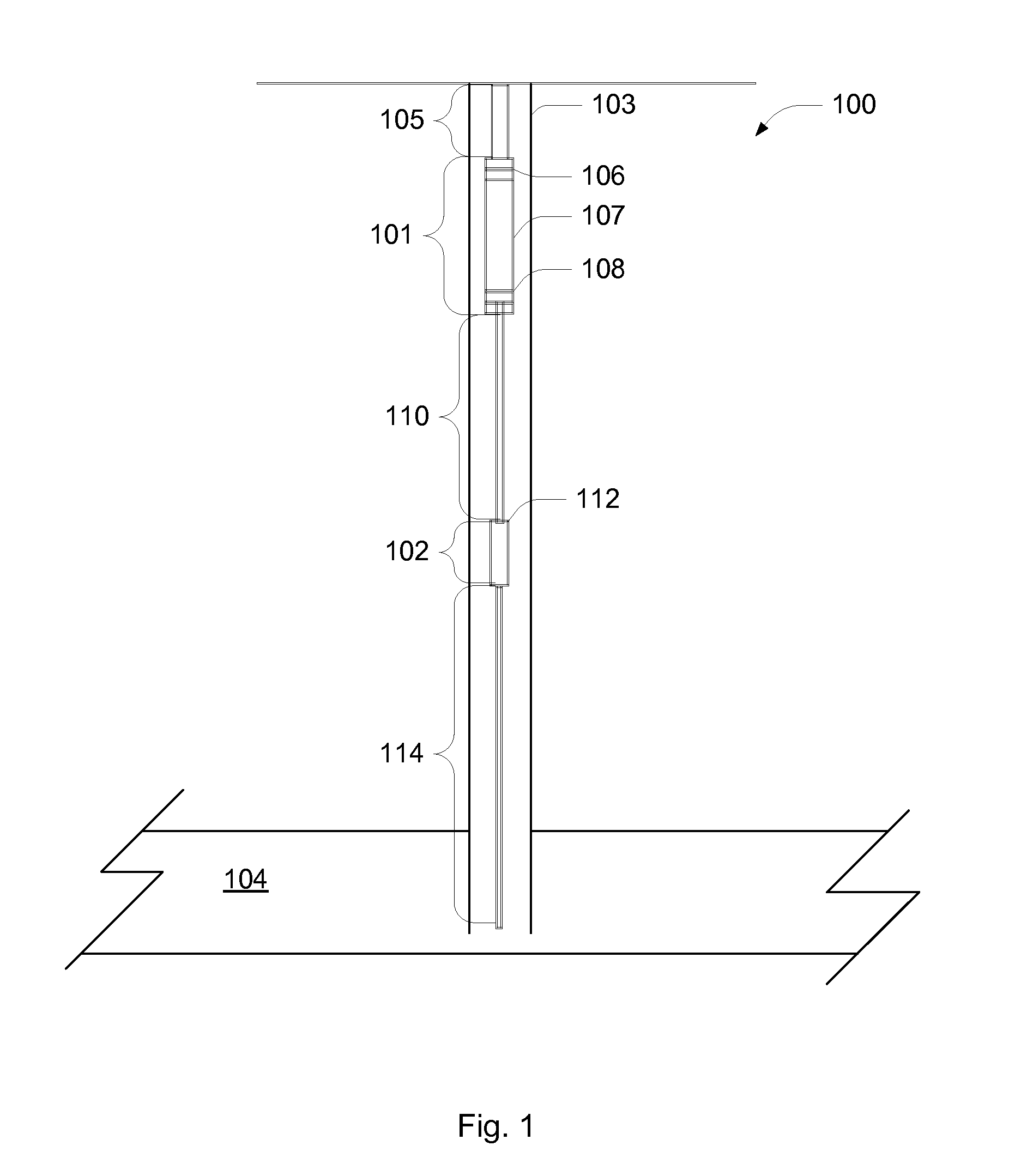
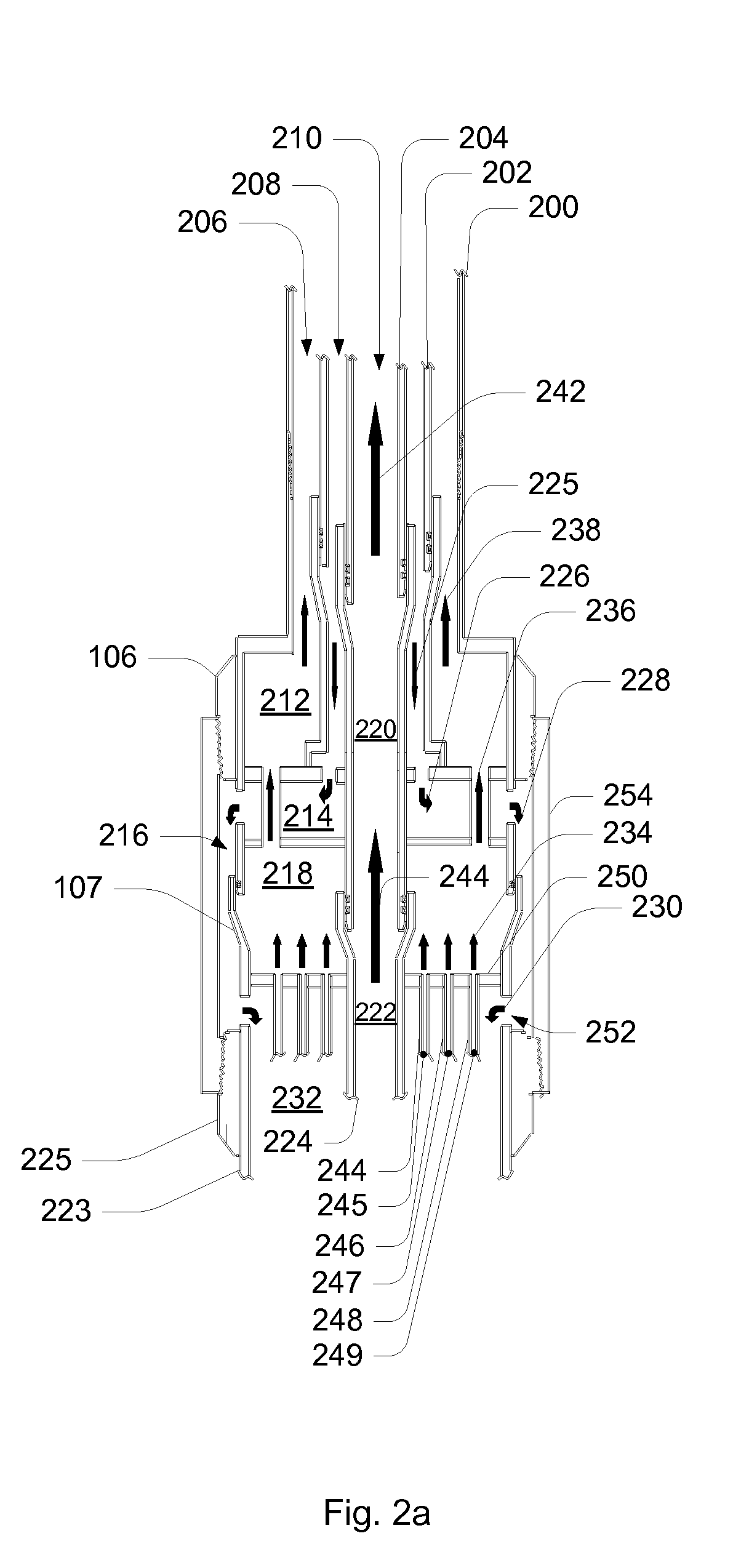
[0022]FIG. 1 is a schematic diagram of a well completion system in accordance with an exemplary embodiment of the invention. The well completion system 100 includes two subsurface sections, a heat exchanger section 101 and a fluidically powered pumping section 102, that extend into a well bore 103. As depicted in the diagram, the wellbore is intended for production of geothermally heated brine from a subsurface production zone 104; however, it is to be understood that the well completion system is not limited to only geothermal applications.

[0023]The well completion system 100 uses concentric tubing strings having three concentric pipes or tubing strings to create independent flow paths from the production zone 104 to the surface. A separate device or flow loop can be installed at the lower end of the concentric tubing strings to create a pressure isolated, continuous, flow loop from the surface to the underground end of the concentric tubing strings. The well completion system 100 ...


PUM


Abstract

A concentric tubing well completion method and a subsurface annular flow crossover system are provided. The well completion method creates at least three separate, pressure isolated annular flow channels in a wellbore. The subsurface crossover provides for switching fluid flow between the annular flow channels within the completed well. The crossover system can be used in conjunction with other subsurface equipment to more efficiently manage fluid flows in the completed well. For example, fluid from any subsurface reservoir or separate reservoirs can be delivered to the surface. In addition, flow paths can be provided for a fluid circulation loop from the surface, a subsurface fluid lifted to the surface or a fluid moved to a different depth in the well for reinjection. The subsurface crossover also provides a method to shift the fluids from one annular fluid channel to another. The subsurface annular flow crossover system also allows the installation of a device at any intermediate depth in the well while allowing fluid flow past the device thus eliminating the disruption or blocking of the flow for the purposes of heat and produced fluid extraction. For example, the crossover can be used to maintain separation between a working fluid and produced fluids in a subsurface heat exchanger used in a geothermal well or a subsurface turbomachinery such as a subsurface pump.

Description

BACKGROUND[0001]1. Field of the Invention[0002]The present invention relates generally to subsurface equipment for fluid production wells and more particularly to managing fluid flow in annular flow channels.[0003]2. Description of the Related Art[0004]Wellbores are often provided with separate multiple flow channels for moving fluids into and out of subsurface reservoirs. For example, a single injection well may be required to provide injection fluids to two or more layers in a reservoir in which case two separate flow channels are required. As another example, a single wellbore may be used to provide both a means for producing fluid from a reservoir and also provide a supply and return conduit for supplying a working fluid to a subsurface device.[0005]One way of separating the flow channels is to use separate tubing strings in parallel and placed into a single wellbore. This method is useful for shallow wells having low flow rates but is impractical for wells having higher flow ra...

Claims


Application Information

Patent Timeline
Patent Type & Authority Applications(United States)
IPC IPC(8): E21B17/04E21B17/00E21B36/00E21B17/042
CPCE21B17/18E21B21/103E21B43/129E21B36/001E21B43/12E21B34/00
Inventor RING, GARY ALLEN
Owner GREENFIRE ENERGY
Why Eureka
Try Eureka