Movable magnet type linear motor with heat-dissipating assembly

Active Publication Date: 2011-02-03
HIWIN MIKROSYST
View PDF5 Cites 18 Cited by
  • Summary
  • Abstract
  • Description
  • Claims
  • Application Information

AI Technical Summary

Benefits of technology

[0008]Another objective of the present invention is to provide a movable magnet type linear motor with a mover heat-dissipating assembly, wherein the h

Problems solved by technology

Moreover, end covers sealing the whole housing 3 to protect the coil 4 and other inner components from dust, water and oil, cause disfavor to aeration and heat dissipation.
Consequently, heat generated by the coil 4 can only be transmitted to the housing 3 by natural gas t

Method used


Image

  • Movable magnet type linear motor with heat-dissipating assembly
  • Movable magnet type linear motor with heat-dissipating assembly
  • Movable magnet type linear motor with heat-dissipating assembly

Examples


Example

[0017]While a preferred embodiment provided hereinafter for illustrating the concept of the present invention as described above, it is to be understood that the components of the embodiment shown in the accompanying drawings are depicted for the sake of easy explanation and need not to be made in scale.

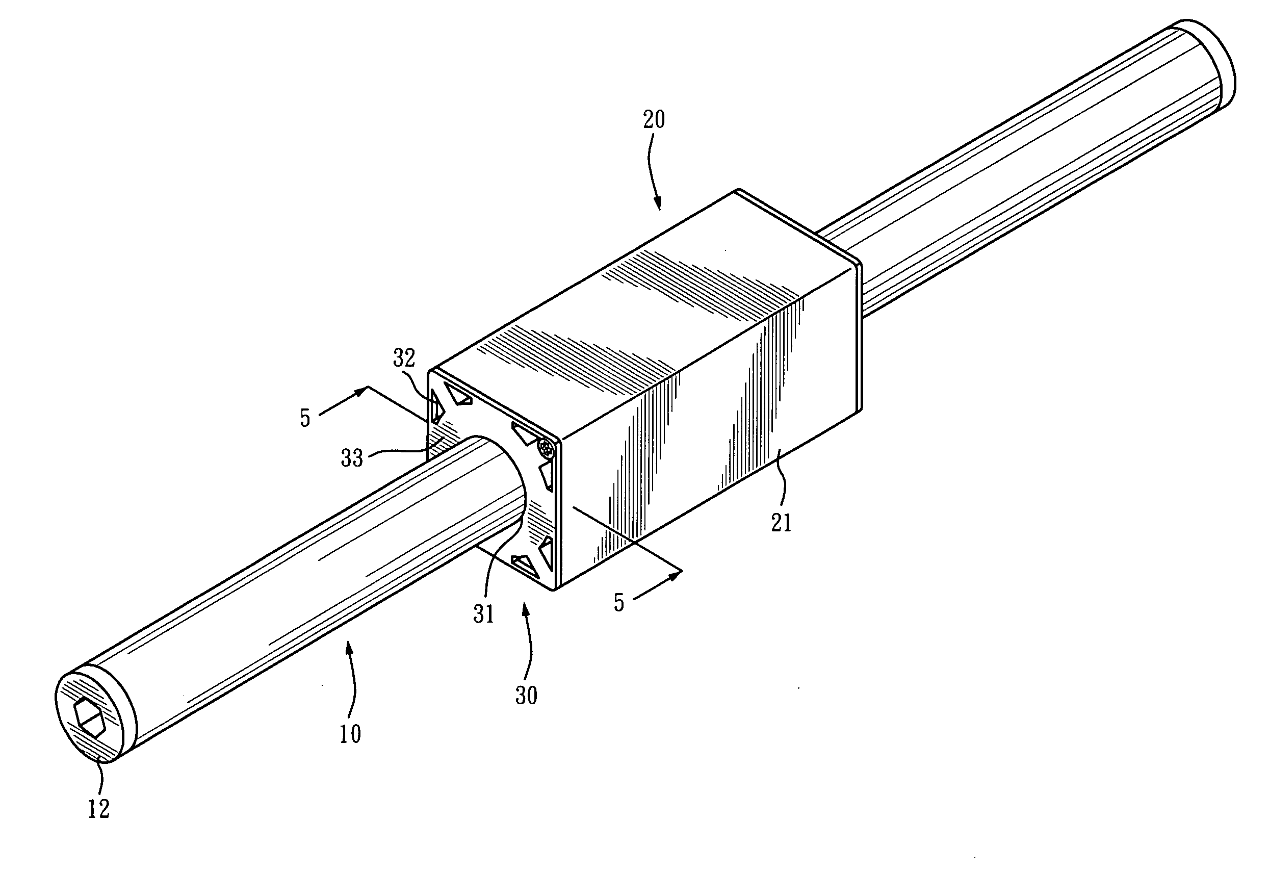
[0018]Please refer to FIGS. 3 through 5 for a movable magnet type linear motor, which includes a stationary inner stator 10, a mover 20, and two end covers 30,

[0019]Therein, the stationary inner stator 10 includes a hollow tube filled with a plurality of permanent magnets 11. Two plugs 12 are attached to two opposite ends of the inner stator 10 so as to retain the permanent magnets 11 in the hollow tube.

[0020]The mover 20 is constructed form a hollow housing 21 that has two openings 211 formed at two opposite ends thereof. A coil seat 22 in the hollow housing 21 includes an accommodating space 221. A plurality of heat sink fins 222 are spaced and settled between the coil seat 22 and ...


PUM


Abstract

A movable magnet type linear motor with a mover heat-dissipating assembly includes a mover having a housing receiving therein a coil seat for holding a coil, openings being formed at two opposite ends of the housing, end covers being attached to the openings and having central holes so as to allow an inner stator to pass through the holes, wherein a plurality of heat dissipating channels are provided between the coil seat and the housing while the end covers have plural heat dissipating holes corresponding to the heat dissipating channels so that external cool air is allowed to enter the housing through the heat dissipating holes and the heat dissipating channels, thereby cooling the mover.

Description

BACKGROUND OF THE INVENTION[0001]1. Technical Field[0002]The present invention relates to movable magnet type linear motors, and more particularly, to a movable magnet type movable magnet type linear motor having a mover equipped with a heat-dissipating assembly.[0003]2. Description of Related Art[0004]FIGS. 1 and 2 illustrate a known movable magnet type linear motor, which comprises a stationary inner stator 1 that is structurally a hollow tube filled with a plurality of permanent magnets, a mover 2 that is constructed form a housing 3 accommodating therein a mover coil 4, wherein two end covers 6 are provided to seal two openings 5 at opposite ends of the housing 3 and each said end cover 6 is centrally formed with a hole 7 so that the stationary inner stator 1 is allowed to axially pass through and get slidably received in the mover 2. When a current flows through the mover coil 4, the mover coil 4 produces a magnetic field to interact with the permanent magnets inside the statio...

Claims


Application Information

Patent Timeline
IPC IPC(8): H02K41/03
CPCH02K5/15H02K41/03H02K5/20H02K5/207
Inventor CHAO, CHIH-HSIENCHENG, FU-YUAN
Owner HIWIN MIKROSYST
Why Eureka
Try Eureka