Power generator

Inactive Publication Date: 2011-02-03
SCHULTE DAVID J
View PDF52 Cites 4 Cited by
  • Summary
  • Abstract
  • Description
  • Claims
  • Application Information

AI Technical Summary

Benefits of technology

[0008]According to the preferred embodiment hereof, the present invention provides a power generator for generating electricity comprising: (a) a core having an interior chamber, the interior chamber having a top portion and a bottom portion, and the core being filled with a volume of a gas; (b) a frequency generator for resonating the gas at a hig

Problems solved by technology

However, some of these fuels are obtained by purchase from foreign countries, and national security concerns exist as to the power which this gives to individuals of concern.
Also, concerns exist among the public as to the by-products which result from burning these fuels, and there are concerns as to the world's finite supplies of some of these fuels.
While the development of nuclear power technology has advanced significantly since catastrophes such as Three Mile Island, such accidents have tainted the public's perception of generating electricity by nuclear power.
As a result of the political hurdles that proponents of nuclear energy now face, the world's production of electricity by nuclear power has leveled off since the Chernobyl accident in 1986.

Method used


Image

  • Power generator
  • Power generator
  • Power generator

Examples


Embodiment Construction

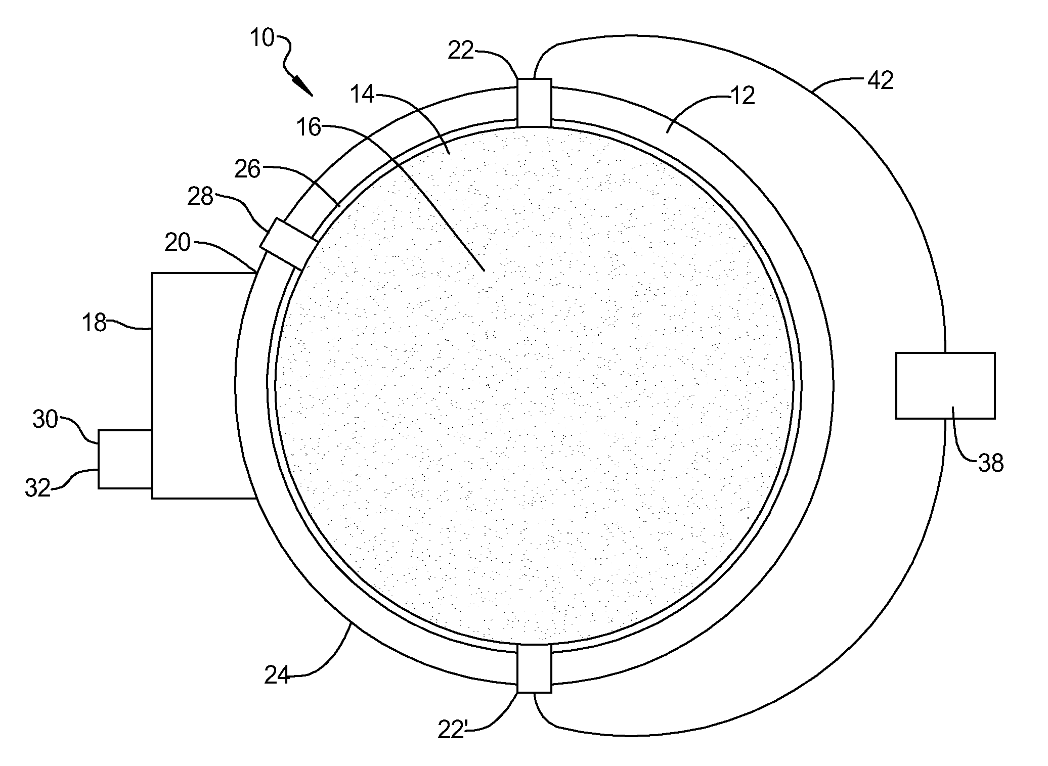
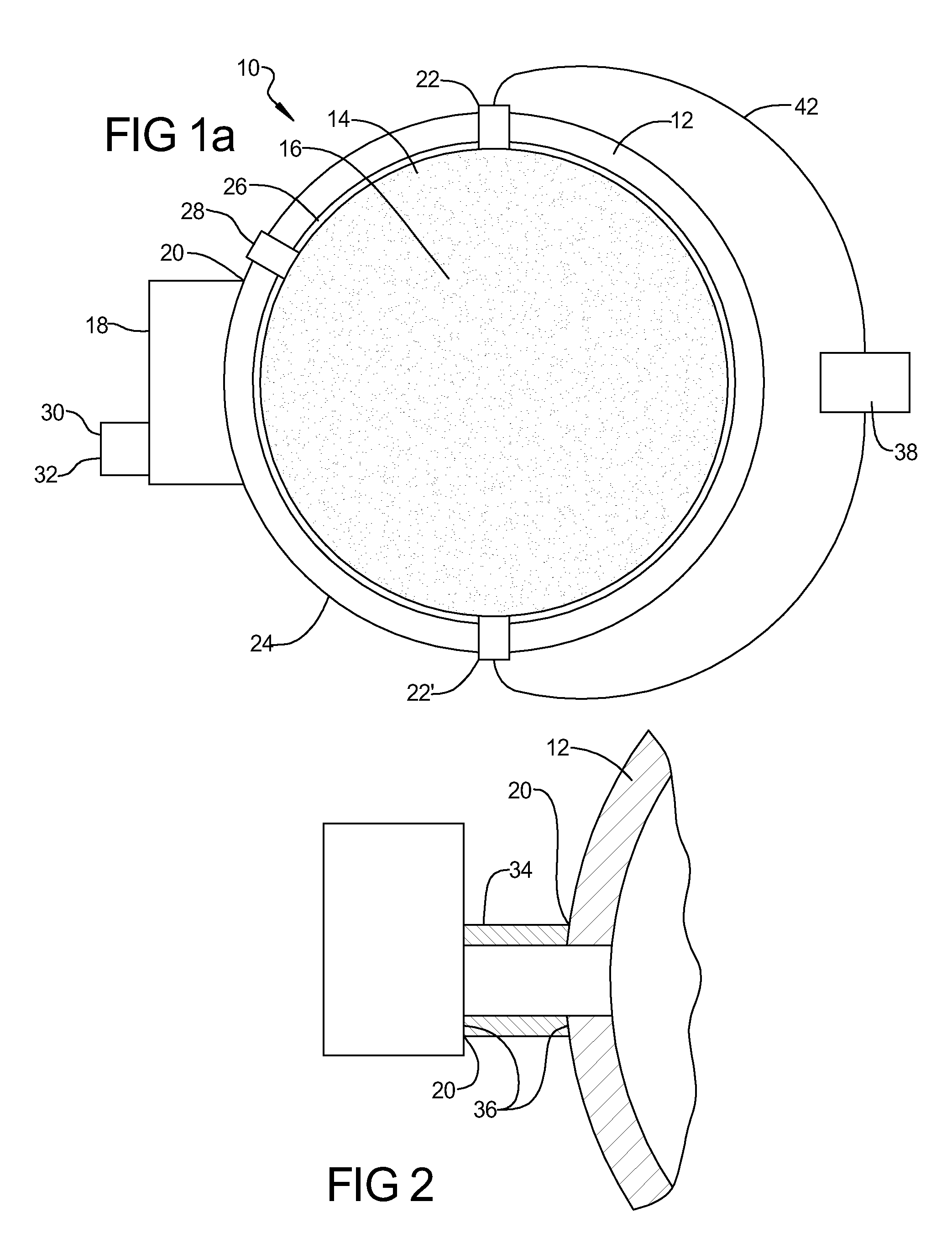
[0015]In accordance with a first embodiment of the present invention and as shown generally in FIG. 1A, there is provided a power generator 10 for generating electricity comprising a core 12 having an interior chamber 14 which is filled with a volume of a gas 16, a frequency generator 18 for resonating the gas 16 at a high frequency, means for securing 20 the frequency generator 18 to the core 12; and a pair of electrical conductors 22,22′ connected to the core 12 for conducting the generated electricity away from the core 12.

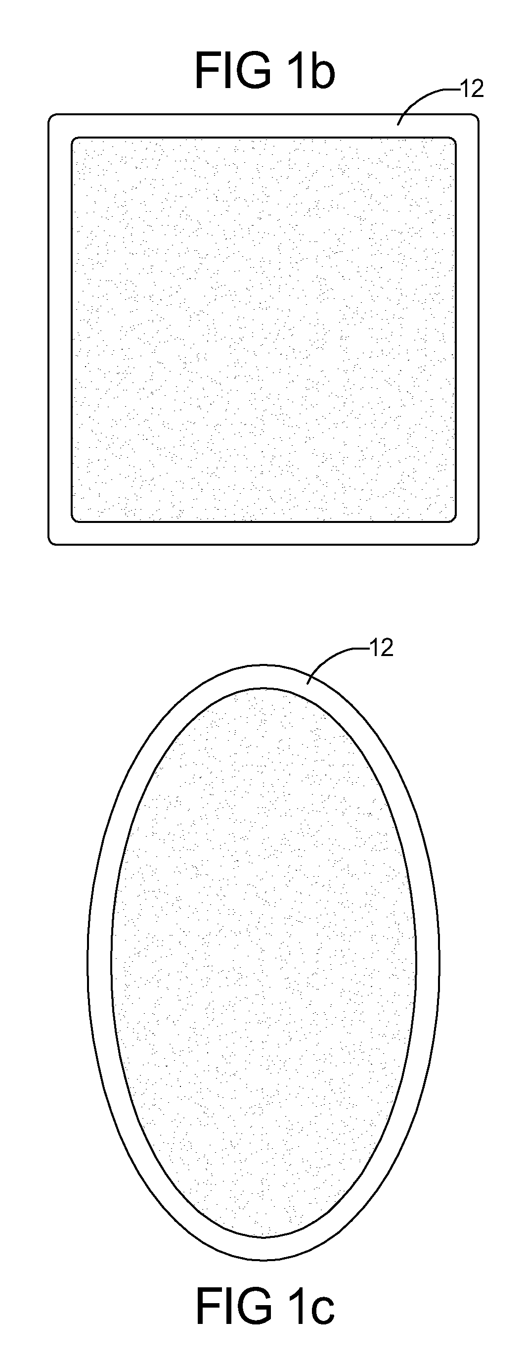
[0016]The core 12 includes the interior chamber 14 and an exterior 24. The core 12 can be of any shape which is suitable for use herewith, for example, spherical, oval, oblong, square, rectangular, pyramidal, etc. The core 12 can be any suitable shape so long as the gas 16 can achieve a standing wave resonance. The exterior 24 of the core 12 can also be shaped so that the exterior 24 geometry matches that of the interior chamber 14. The core 12 comprises any su...


PUM


Abstract

The present invention provides a power generator for generating electricity comprising a core having an interior chamber, the interior chamber having a top portion and a bottom portion. The core is filled with a volume of a gas. A frequency generator is provided for resonating the gas at a high frequency, and means for securing the frequency generator to the core are provided as well. In addition, a pair of electrical conductors is connected to the core to conduct the flow of electricity away from the core.

Description

BACKGROUND OF THE INVENTION[0001]1. Field of the Invention[0002]The present invention pertains to a power generator for generating electricity. More particularly, the present invention pertains to a power generator for generating electricity by resonating a gas at a high frequency.[0003]2. Description of the Prior Art[0004]Various types of power generators exist in the prior art which have been used for many years. For example, fossil fuel power plants which burn fossil fuels to generate electricity have been in common use for many years. Examples of such power plants burn fuels, such as methane, coal, or petroleum, to convert combustion products (e.g., heat) into mechanical motion, which is then converted to electricity. However, some of these fuels are obtained by purchase from foreign countries, and national security concerns exist as to the power which this gives to individuals of concern. Also, concerns exist among the public as to the by-products which result from burning thes...

Claims


Application Information

Patent Timeline
IPC IPC(8): H02K35/00H02K53/00
CPCH02N11/008
Inventor SCHULTE, DAVID J.
Owner SCHULTE DAVID J
Why Eureka
Try Eureka