Magneto-resistance effect element and sensor

a technology of magneto-resistance effect and element, applied in the direction of magnetic measurement, instruments, measurement devices, etc., to achieve the effect of improving sensing accuracy

Active Publication Date: 2011-02-03
TDK CORPARATION
View PDF16 Cites 14 Cited by
  • Summary
  • Abstract
  • Description
  • Claims
  • Application Information

AI Technical Summary

Benefits of technology

[0009]An object of the present invention is to provide a magneto-resistance effect element configured to enable improvement in sensing accur...

Problems solved by technology

The following matters are obsta...

Method used


Image

  • Magneto-resistance effect element and sensor
  • Magneto-resistance effect element and sensor
  • Magneto-resistance effect element and sensor

Examples


Embodiment Construction

[0028]Embodiments of the present invention will be described below.

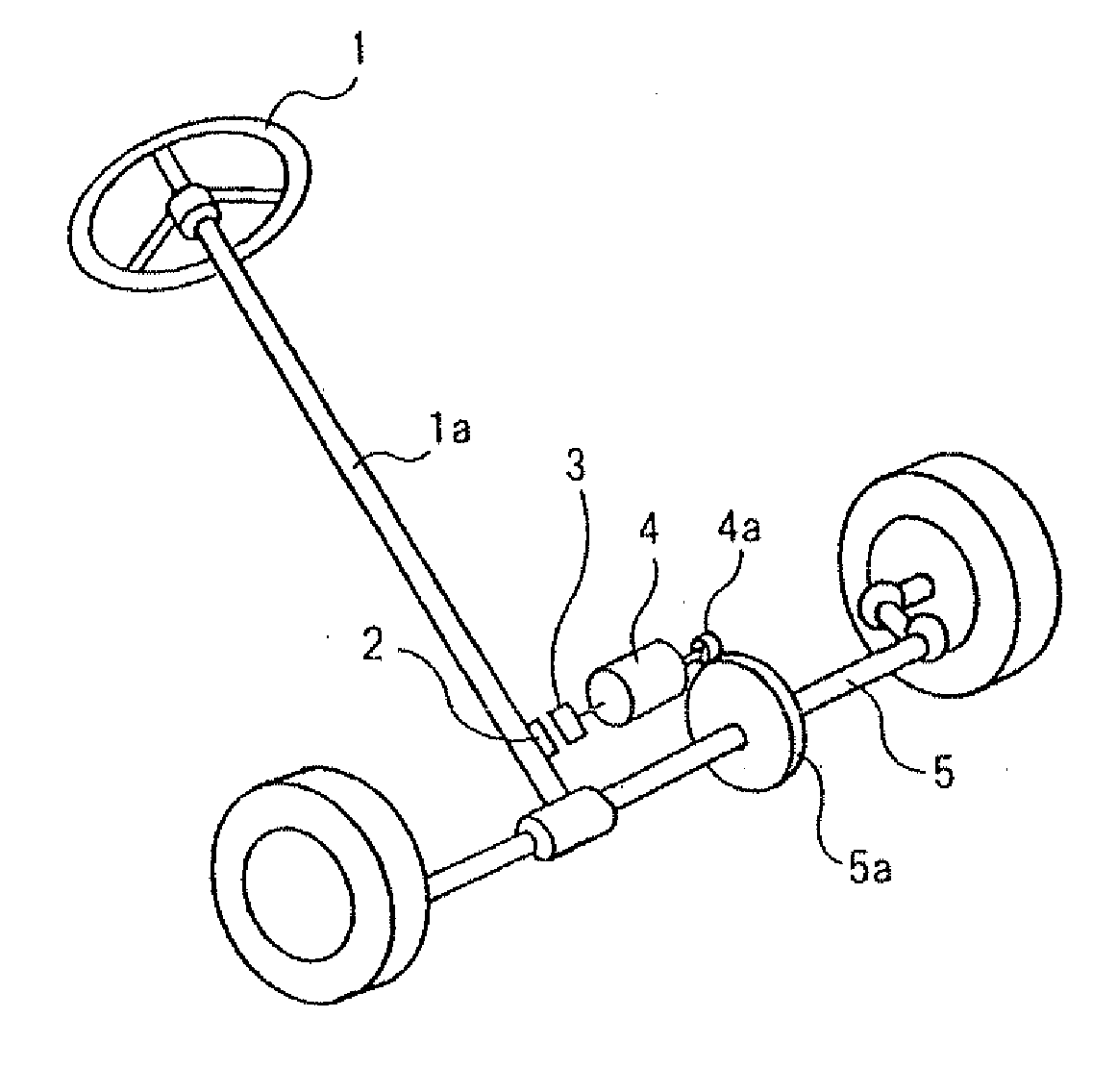
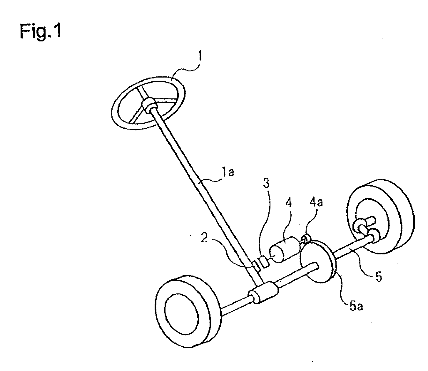
[0029]First, the general configuration of a sensor according to the present invention, that is, an example of a sensor configured to sense the angle of a sense target member, will be described. As schematically shown in FIG. 1, permanent magnet 2 is mounted on a part of shaft 1a of steering wheel 1 in a vehicle. At a position opposite to magnet 2, sensing circuit 3 is fixed to a mounting member (not shown in the drawings). Magnet 2 and sensing circuit 3 are the main components of the sensor. Sensing circuit 3 is connected to motor 4 via a control circuit (not shown in the drawings). Pinion 4a of motor 4 is coupled to gear 5a attached to steering axle 5. Steering axle 5 is coupled to shaft 1a of steering wheel 1.

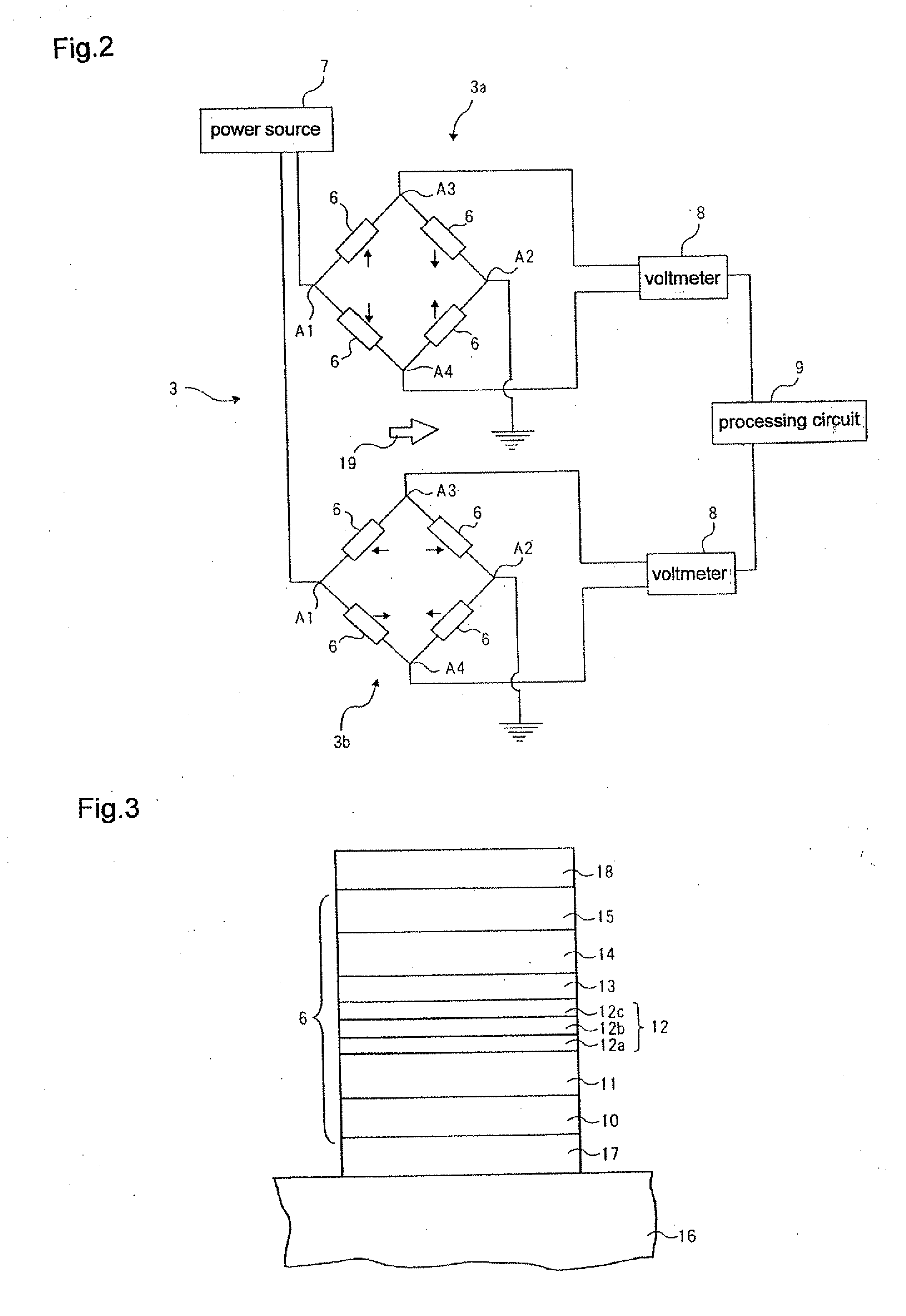
[0030]The configuration of sensing circuit 3 is schematically shown in FIG. 2. Sense circuit 3 includes two Wheatstone bridges 3a and 3b. In the circuitry design shown in FIG. 2, each of Wheatstone bridges 3a ...


PUM


Abstract

A magneto-resistance effect element for a sensor to sense a variation in externally applied magnetism includes a pinned layer having a fixed magnetization direction, a free layer having a magnetization direction which varies in response to an external magnetic field, and an intermediate layer provided between the pinned layer and the free layer. The pinned layer has a planar shape which is long in the fixed magnetization direction and which is short in a direction orthogonal to the fixed magnetization direction. Moreover, the pinned layer preferably has a planar shape in which the pinned layer is divided into a plurality of sections.

Description

BACKGROUND OF THE INVENTION[0001]1. Field of the Invention[0002]The present invention relates to a magneto-resistance effect element and a sensor.[0003]2. Description of the Related Art[0004]Sensors using magneto-resistance effect (MR) elements have sometimes been used to sense the angle of rotation of a steering wheel in a vehicle (see Japanese Patent Application Laid-open No. 2006-29792A, Japanese Patent Application Examined Publication No. 7-119619B, Japanese Patent No. 3017061, and “Development of Highly Sensitive Terrestrial Sensor using TMR Junctions”, Kou, F. et al., Journal of the Magnetics Society of Japan Vol. 32, No. 3, 2008, published by The Magnetic Society of Japan). Specifically, the sensor is configured such that for example, a magnet is mounted on the shaft of the steering wheel and such that a sensing circuit including a Wheatstone bridge with a plurality of MR elements connected to each other is fixed at a position opposite to the magnet. When a driver turns the s...

Claims


Application Information

Patent Timeline
IPC IPC(8): G01R33/09
CPCG01R33/091G01R33/0005
Inventor YAMAZAKI, HIROSHIHIRABAYASHI, HIRAKUOHTA, NAOKI
Owner TDK CORPARATION
Why Eureka
Try Eureka