
Synthetic image formation via signal processing for vignetted optoelectroinc arrays, lensless cameras, and integrated camera-displays

a technology of optoelectroinc array and signal processing, which is applied in the field of electromechanical image formation, can solve the problems of requiring appreciable depth or thickness of the optical imaging system, and achieve the effect of more natural telepresence experiences and direct eye conta

Inactive Publication Date: 2011-02-03
NRI R&D PATENT LICENSING LLC
View PDF2 Cites 4 Cited by
  • Summary
  • Abstract
  • Description
  • Claims
  • Application Information

AI Technical Summary

Benefits of technology

"The present patent describes a system and method for creating images using data from light sensor arrays. This system does not require a large lens or physical separation distances, and can be integrated into flat or curved screens for more direct eye contact and natural telepresence experiences. The sensor array can have a micro-optic structure, such as micro-lenses or a perforated optical mask, to capture different parts of the observed scene. The LED array can be sequentially selected to operate in different modes, and the image formation is done by performing linear mathematical transformations on the sensor measurements. The resultant image formation is in a signal processing domain, allowing for modification or modulation as a function of control signals. The technology can provide new understanding and applications of vision in organisms with single-lens compound-eyes, which are thought to have limited resolution."

Problems solved by technology

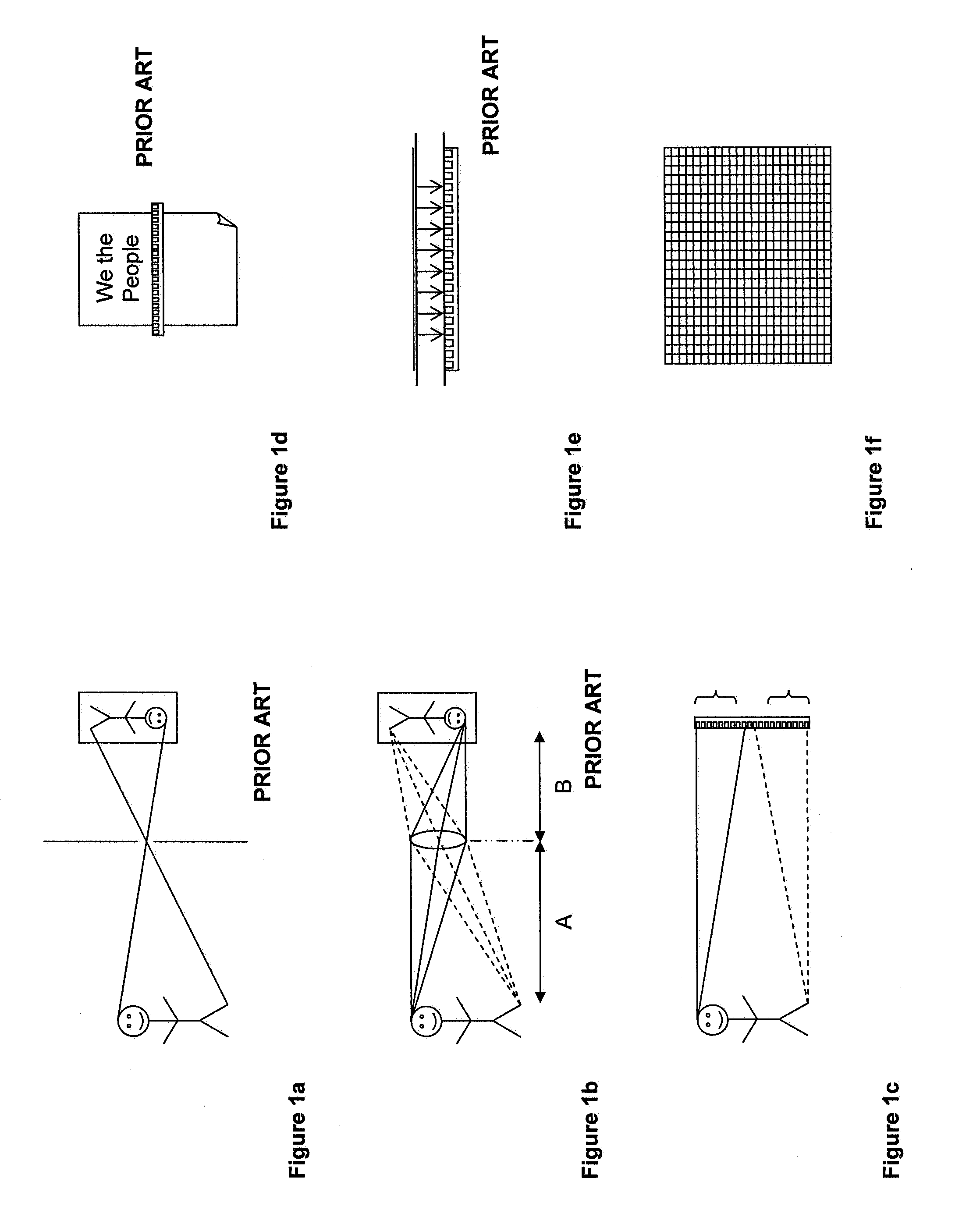
Physical limitations of these and other aspects of camera technology thus create a required appreciable depth or thickness of the optical imaging system.

Method used


Image

  • Synthetic image formation via signal processing for vignetted optoelectroinc arrays, lensless cameras, and integrated camera-displays
  • Synthetic image formation via signal processing for vignetted optoelectroinc arrays, lensless cameras, and integrated camera-displays
  • Synthetic image formation via signal processing for vignetted optoelectroinc arrays, lensless cameras, and integrated camera-displays

Examples


Embodiment Construction

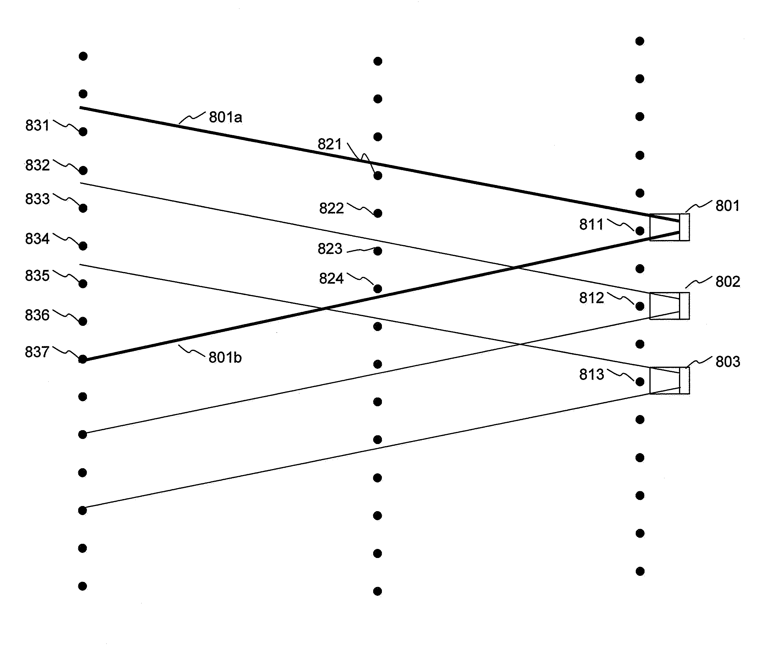
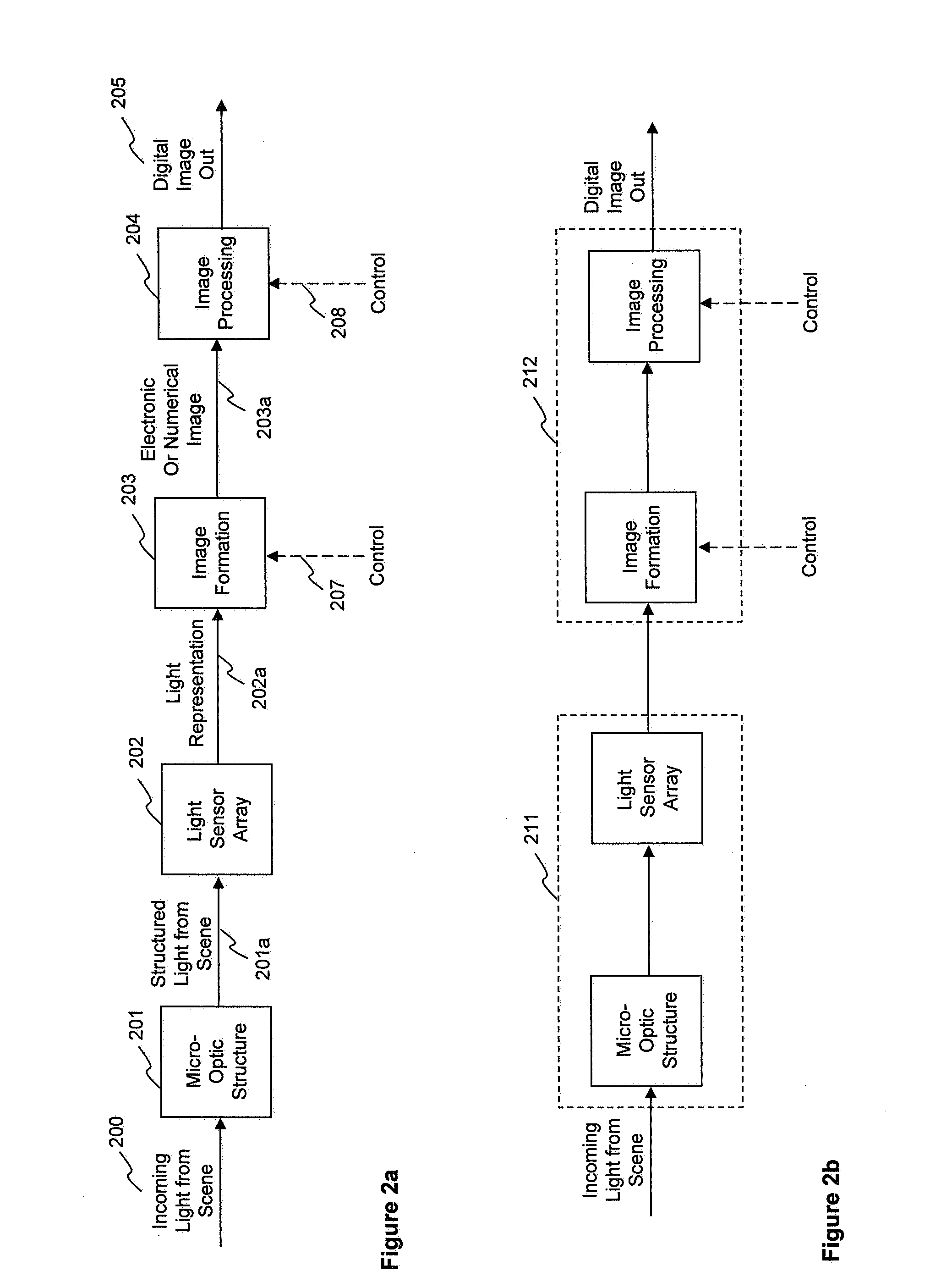
[0078]Referring to FIG. 2a, incoming light 200 from a visual scene is optically organized, filtered, etc. by at least one micro-optic structure 201 to provide light field 201a suitably structured for incoming presentation to a light sensor array 202. The light sensor array 202 produces a representation (electrical, digital, numeric, etc.) 202a of the incoming light field 201a suitable for presentation to a signal processing operation 203 configured to provide image formation. In an example embodiment, the representation 202a of the incoming light field is not a visually useful electronic or digital image as it comprises pixels having amplitude values resulting from summations of light levels across entire individual image vignettes. In an example embodiment, the image formation signal processing operation 203 comprises a linear transformation whose character depends on the optical organization the micro-optic structure 201 imposes on the incoming light 200 from the visual scene. The...


PUM


Abstract

Algorithms and methods for performing electronic image formation and refinement from overlapping measurement vignettes captured by an array of image sensors and associated micro-optics are presented. The invention is directed to a new type of image formation system that combines readily-fabricated micro-optical structures, a two-dimensional image sensor array with electronic or digital image processing to actually construct the image. Image formation is performed without a conventional large shared lens and associated separation distance between lens and image sensor, resulting in a “lensless camera.”In an application, a readily fabricatable LED array is used as a light-field sensor. In an application, the LED array further serves as a color “lensless camera.” In an application, the LED array also serves as an image display. In an application, the LED array further serves as a color image display. In an embodiment, one or more synergistic features of an integrated camera / display surface are realized.

Description

CROSS-REFERENCE TO RELATED APPLICATION[0001]This regular U.S. patent application is a continuation of U.S. application Ser. No. 12 / 471,275 filed May 22, 2009; which claims the benefit of priority under 35 U.S.C. 119 from provisional U.S. patent application No. 61 / 128,968, filed on May 25, 2008. Application Ser. Nos. 12 / 471,275 and 61 / 128,968 are fully incorporated herein by reference for all purposes.FIELD OF THE INVENTION[0002]This invention pertains to electronic image formation and refinement from overlapping measurement vignettes captured by an array of image sensors and associated micro-optics. The present invention is directed in major part to an alternate image formation system that combines readily-fabricated micro-optical structures, a two-dimensional image sensor array with electronic or digital image processing to actually construct the image.BACKGROUND OF THE INVENTION[0003]Image formation as used in camera obscura and photography dates back to the pinhole camera discove...

Claims


Application Information

Patent Timeline
Patent Type & Authority Applications(United States)
IPC IPC(8): H04N5/225
CPCH04N5/225H04N5/374H04N5/3696H04N5/30H04N25/76H04N23/955H04N23/00H04N25/702
Inventor LUDWIG, LESTER F.
Owner NRI R&D PATENT LICENSING LLC
Learn More