Multi-Functional Aircraft Structures

a multi-functional, aircraft technology, applied in the field of structures, can solve the problems of composite materials providing the service life of various components of aircraft, weight of aircraft is a factor in the operating expense and performance of aircraft,

Active Publication Date: 2011-02-03
THE BOEING CO
View PDF99 Cites 63 Cited by
  • Summary
  • Abstract
  • Description
  • Claims
  • Application Information

AI Technical Summary

Problems solved by technology

The weight of an aircraft is a factor in the operating expense and performance of the aircraft.
Fu

Method used


Image

  • Multi-Functional Aircraft Structures
  • Multi-Functional Aircraft Structures
  • Multi-Functional Aircraft Structures

Examples


Embodiment Construction

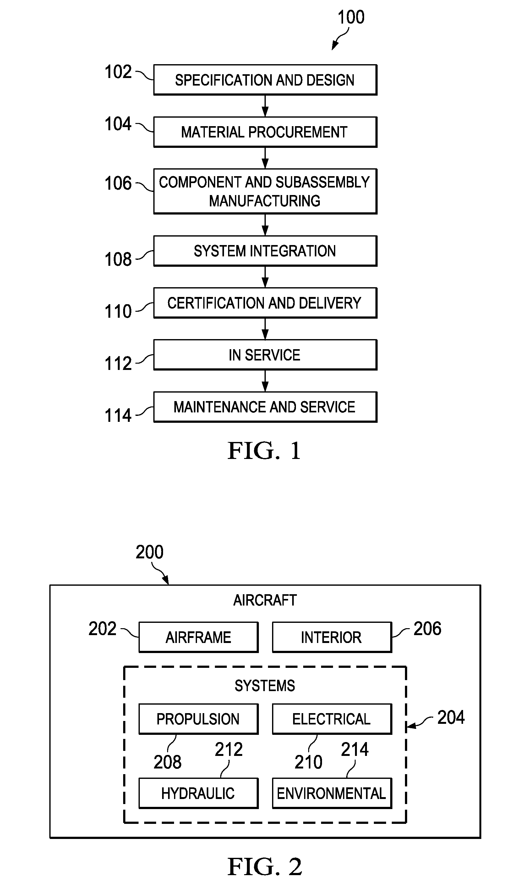
[0028]Referring more particularly to the drawings, embodiments of the disclosure may be described in the context of aircraft manufacturing and service method 100 as shown in FIG. 1 and aircraft 200 as shown in FIG. 2. Turning first to FIG. 1, an illustration of an aircraft manufacturing and service method is depicted in accordance with an illustrative embodiment. During pre-production, aircraft manufacturing and service method 100 may include specification and design 102 of aircraft 200 in FIG. 2 and material procurement 104.

[0029]During production, component and subassembly manufacturing 106 and system integration 108 of aircraft 200 in FIG. 2 takes place. Thereafter, aircraft 200 in FIG. 2 may go through certification and delivery 110 in order to be placed in service 112. While in service 112 by a customer, aircraft 200 in FIG. 2 is scheduled for routine maintenance and service 114, which may include modification, reconfiguration, refurbishment, and other maintenance or service.

[0...


PUM

PropertyMeasurementUnit
Structureaaaaaaaaaa
Shapeaaaaaaaaaa

Abstract

A method and apparatus for manufacturing a composite structure. A filler material with a barrier material for a channel in the filler material is formed. A composite material and the filler material with the barrier material are laid up onto a tool in a shape of the composite structure. The composite material and the filler material in the shape of the composite structure are cured.

Description

BACKGROUND INFORMATION[0001]1. Field:[0002]The present disclosure relates generally to structures and, in particular, to structures for use in aircraft. Still more particularly, the present disclosure relates to structures that have multiple functions in an aircraft.[0003]2. Background:[0004]The weight of an aircraft is a factor in the operating expense and performance of the aircraft. For example, an aircraft with a lighter weight may consume less fuel and may be able to travel for longer distances, as compared to an aircraft with a greater weight. For example, performance, such as stall speed, maximum range air speed, maximum endurance air speed, rate of climb, maneuvering speed, and other performance factors are related to the weight of an aircraft.[0005]In an effort to reduce weight and improve performance, the commercial aircraft industry has increased the use of composite materials. In this effort, aircraft are being designed and manufactured with greater and greater percentag...

Claims


Application Information

Patent Timeline
IPC IPC(8): B32B3/12B32B3/30B32B3/26B32B37/24
CPCB29C70/30B29C70/865B29L2031/3076B64C1/061B64C1/064B64C1/065Y10T428/24157B64C2001/0072Y02T50/433Y10T428/24149B29D99/001Y10T428/2457Y10T428/24496B64C1/18B29D99/0017Y02T50/40B29C70/302
Inventor MCCARVILLE, DOUGLAS A.GUZMAN, JUAN C.ROTTER, DANIEL M.
Owner THE BOEING CO
Why Eureka
Try Eureka