Eureka AIR delivers breakthrough ideas for toughest innovation challenges, trusted by R&D personnel around the world.

HDMI cable connector

a cable connector and hdmi technology, applied in the direction of coupling device connection, coupling protective earth/shielding arrangement, electrical equipment, etc., can solve the problems of increased defectivity rate and higher cost, and achieve the effect of avoiding the increase of defectivity ra

Active Publication Date: 2011-02-03
MOLEX INC
View PDF7 Cites 16 Cited by
  • Summary
  • Abstract
  • Description
  • Claims
  • Application Information

AI Technical Summary

Benefits of technology

[0005]For overcoming the aforementioned deficiencies, an object of the Present Disclosure is to provide a low-cost miniaturized cable connector having a decreased rate of defective products.
[0008]In comparison with the description above, a technical advantage effect of the Present Disclosure is that the connected circuit board, located between the connector and the cable, is accommodated in an insulating inner housing formed by combining the upper and the lower casings. Further, the copper foil covers the periphery of the insulating inner housing to shield electromagnetic interference. Finally, the plastic outer housing is integrally formed. Since the insulating inner housing is non-conductive, the gap between the insulating inner housing and the circuit board may be small enough so as to miniaturize the cable connector. Moreover, the sleeve, designed to be embedded at the periphery of the cable and covered by the outer housing, can function as strain relief, preventing the electrical contact between the cable and the circuit board from being damaged when the cable is stretched under an external force.
[0009]In addition, the upper casing is in combination with the lower casing, forming the insulating inner housing for receiving the connected circuit board. As such, it can protect the electrical properties and the welding spot of the electrical components on the circuit board from disparate impact due to both high temperature and high pressure when forming the inner mold, and thusly avoid the increase of the defectivity rate.

Problems solved by technology

Therefore, the metal inner housing is usually formed with a relative large profile, which negatively affects the miniaturization of the product and results in a higher cost.
If this solution is applied to a cable connector having a connected circuit board, the electrical properties, or the welding spot of electrical components on the circuit board, could suffer due to the high temperature and high pressure associated in forming the inner mold, resulting in an increase of defective products.

Method used


Image

  • HDMI cable connector
  • HDMI cable connector
  • HDMI cable connector

Examples


Embodiment Construction

[0017]While the Present Disclosure may be susceptible to embodiment in different forms, there is shown in the Figures, and will be described herein in detail, specific embodiments, with the understanding that the disclosure is to be considered an exemplification of the principles of the Present Disclosure, and is not intended to limit the Present Disclosure to that as illustrated.

[0018]In the illustrated embodiments, directional representations—i.e., up, down, left, right, front, rear and the like, used for explaining the structure and movement of the various elements of the Present Disclosure, are relative. These representations are appropriate when the elements are in the position shown in the Figures. If the description of the position of the elements changes, however, it is assumed that these representations are to be changed accordingly.

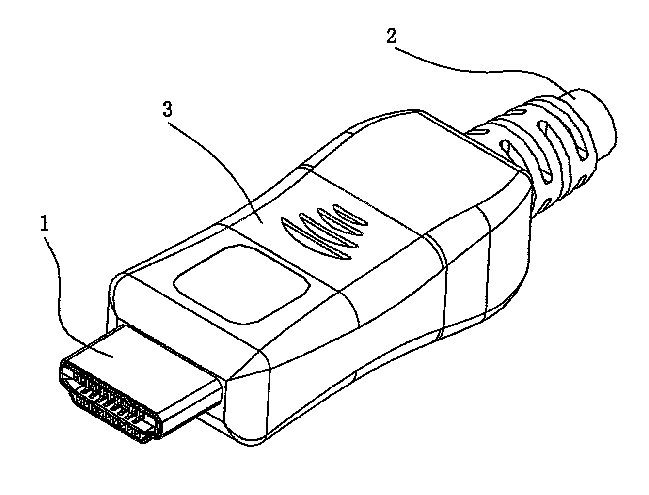
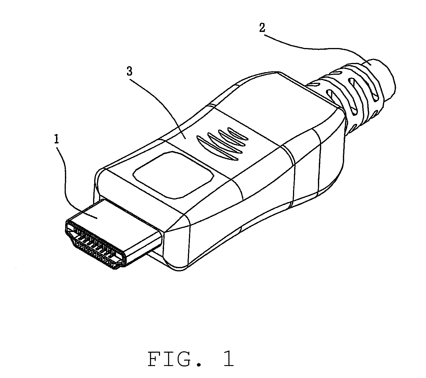
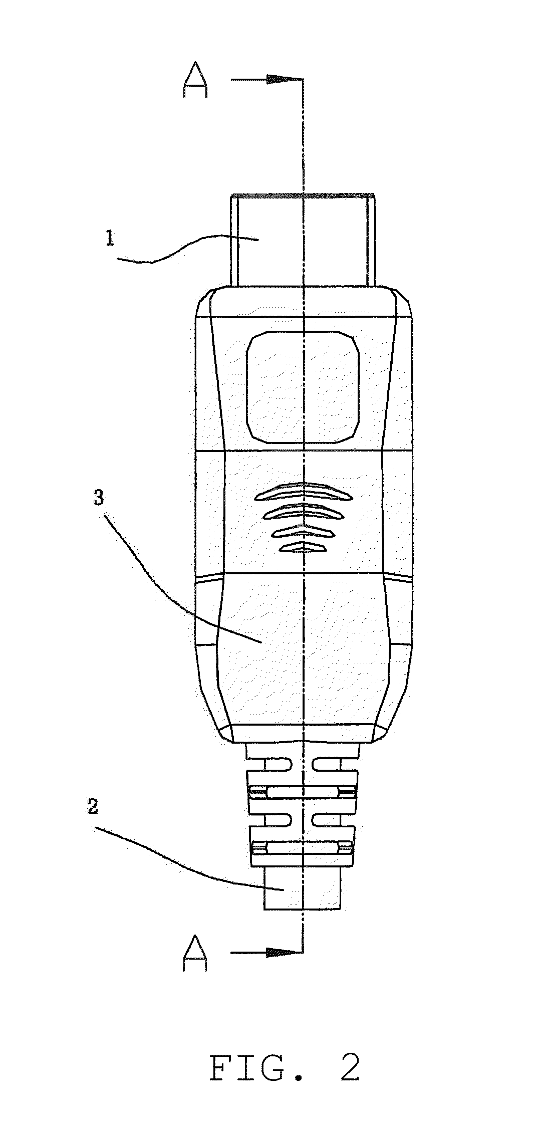
[0019]As illustrated in FIGS. 1-6, the cable connector comprises connector 1, cable 2, outer housing 3, insulating inner housing 4, copper foil...


PUM


Abstract

A cable connector comprising a connector, a cable, a circuit board electrically connecting the connector to the cable, an insulating inner housing and an outer housing. The connector comprises an insulating housing, a plurality of conductive terminals disposed therein and a metal shield mounted on the periphery of the insulating housing. The insulating inner housing comprises upper and lower casings integrally coupled together and a receiving space formed therebetween for accommodating the circuit board. The cable connector comprises a copper foil which covers the periphery of the insulating inner housing. The copper foil is electrically coupled to the metal shield and grounded through the metal shield. Finally, the outer housing envelopes the periphery of the copper foil. Thereby, the cable connector can achieve both miniaturized and a lower cost, while also reducing the rate of defective products.

Description

REFERENCE TO RELATED MATTERS[0001]The Present Disclosure claims priority of prior-filed Chinese Patent Application No. 200920003339.1, entitled “Cable Connector,” and filed 23 Jan. 2009, the contents of which is fully incorporated in its entirety herein.BACKGROUND OF THE PRESENT DISCLOSURE[0002]The Present Disclosure relates generally to an electrical connecting device, and in particular to a cable connector.[0003]Generally, a conventional cable connector comprises a connector, a cable, a connected circuit board and an outer housing. The cable connector is electrically connected to the cable through the connected circuit board. The periphery of the connection portion for the connector and the cable is enveloped by the outer housing. In order to shield electromagnetic interference, it is typical to adopt a metal inner housing for receiving the connected circuit board, located between the connector and the cable, subsequent to forming a plastic outer housing for insulation and manual ...

Claims


Application Information

Patent Timeline
Patent Type & Authority Applications(United States)
IPC IPC(8): H01R13/648
CPCH01R12/62H01R13/6658H01R13/648H01R13/502
Inventor LUO, FU-YONG
Owner MOLEX INC
Why Eureka
Eureka Blog
Learn More