
Method and device for predicting a rechargeable battery's lifetime

a rechargeable battery and lifetime technology, applied in the field of methods and devices for predicting the can solve problems such as the end of batteries, and achieve the effect of precise prediction of the end of life of rechargeable batteries

Inactive Publication Date: 2011-02-03
KONINKLIJKE PHILIPS ELECTRONICS NV
View PDF18 Cites 13 Cited by
  • Summary
  • Abstract
  • Description
  • Claims
  • Application Information

AI Technical Summary

Benefits of technology

[0004]It is an object of the invention to provide a method that allows for a precise prediction of a rechargeable battery's end of life without permanently monitoring the battery's actual use.SUMMARY OF THE INVENTION
[0008]In a preferred embodiment according to the invention, a characteristic which is monotonically changing with time is used as the battery characteristic indicative for battery aging. The benefit of employing a characteristic that changes monotonically with time is that it allows for an appropriate application of methods to construct new data points outside a set of known data points for the battery characteristic indicative for battery aging.
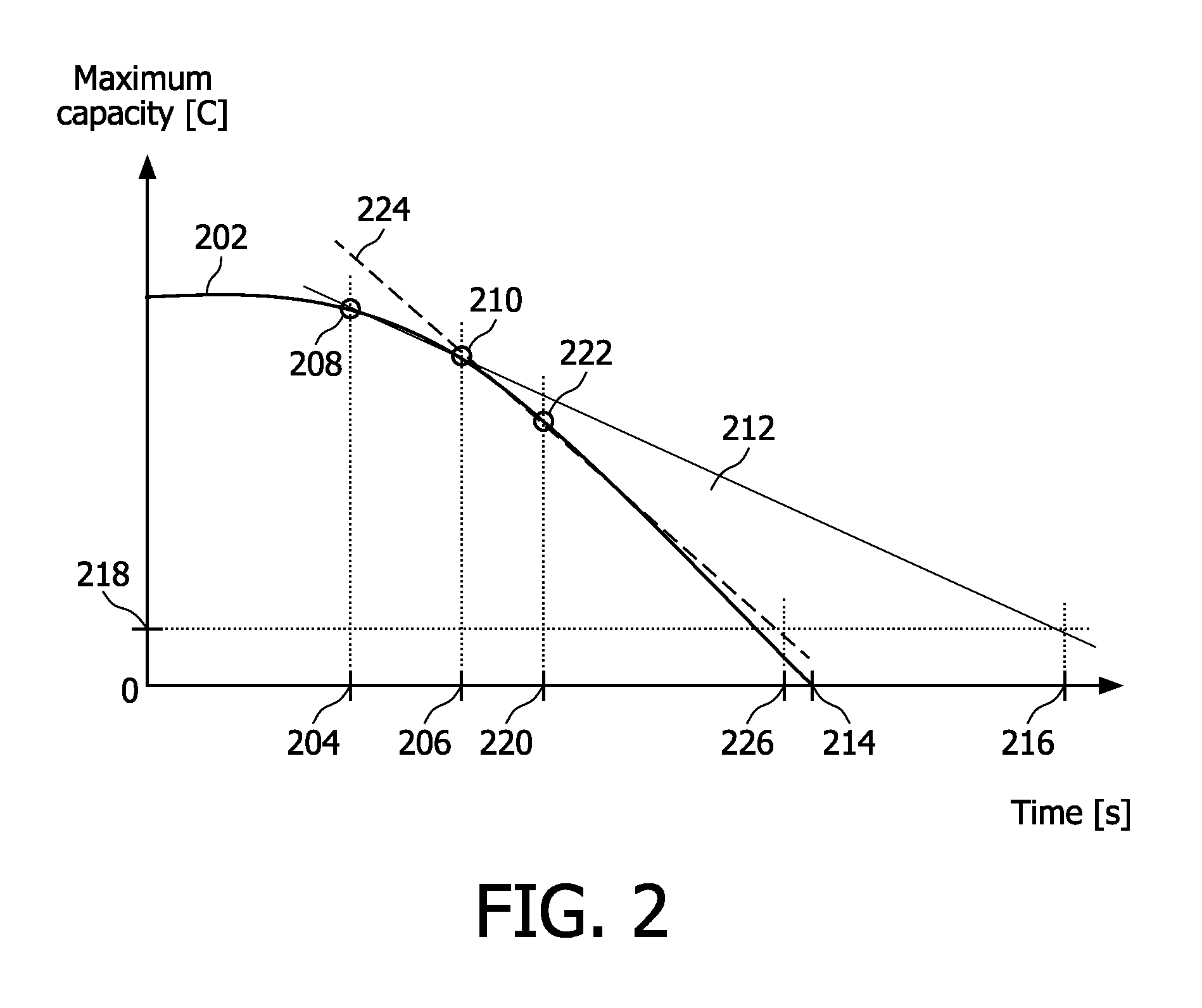
[0009]Hence, in a further embodiment the estimation of the battery's lifetime is based on an extrapolation of data points of the battery characteristic indicative for battery aging. By extrapolating the battery characteristic to a predefined level at which the battery characteristic is agreed to be such that the battery's end of life is reached, the battery's lifetime is estimated. The application of extrapolation techniques reduces the efforts required to appropriately monitor the battery characteristic indicative for battery aging.

Problems solved by technology

Battery aging will eventually culminate into the battery's end of life.

Method used


Image

  • Method and device for predicting a rechargeable battery's lifetime
  • Method and device for predicting a rechargeable battery's lifetime
  • Method and device for predicting a rechargeable battery's lifetime

Examples


second embodiment

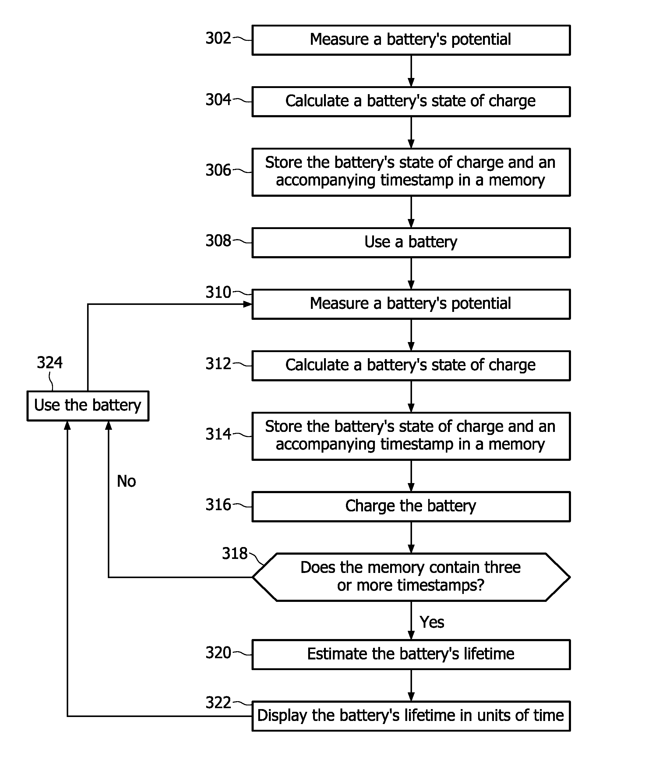
[0039]In a second embodiment according to the invention, the rate of decay for the battery's state of charge is monitored in order to estimate a battery's remaining lifetime. FIG. 3 depicts a flowchart which schematically explains this embodiment. At step 302 the battery's voltage is measured before using the battery employing a voltmeter known per se. During step 302 the battery is operating at substantially small drain currents hence the measured battery's voltage corresponds to a battery's so called equilibrium voltage value which is usually referred to as a battery's EMF. Step 304 contains the determination of a battery's state of charge prior to using the battery on the basis of the battery's voltage measured during step 302 and by employing a look-up table that connects the battery's voltage to the battery's state of charge. Step 306 comprises storing a numerical representation for the battery's maximum capacity and an accompanying timestamp in a memory. Step 308 contains usin...

third embodiment

[0044]In a third embodiment according to the invention, time spans between consecutive points of time at which a battery's state of charge decreases from a predetermined maximum level to a predetermined minimum are monitored in order to estimate a battery's remaining lifetime. FIG. 6 depicts a flowchart which schematically explains this embodiment. Step 602 contains using a battery prior to a first instance of charging the battery. At step 604 the battery's state of charge attains the predefined minimum level at which charging is required. Step 606 comprises storing a numerical representation for an accompanying timestamp in a memory. Step 608 comprises charging the battery to the predefined maximum level using a charger known per se. At step 610 the contents of the memory are retrieved employing methods known per se. In case the memory contains three or more data time stamps, a battery's remaining lifetime is estimated at step 612 through a method explained below.

[0045]FIG. 7 schem...

fourth embodiment

[0049]A fourth embodiment according to the invention is a device 902, see FIG. 9 for determining an end of life for a rechargeable battery. The device 902 comprises a battery charger 904 known per se. The device 902 further comprises a provision 906 for monitoring a battery characteristic indicative for battery aging and a provision 908 for estimating a battery's end of life.


PUM


Abstract

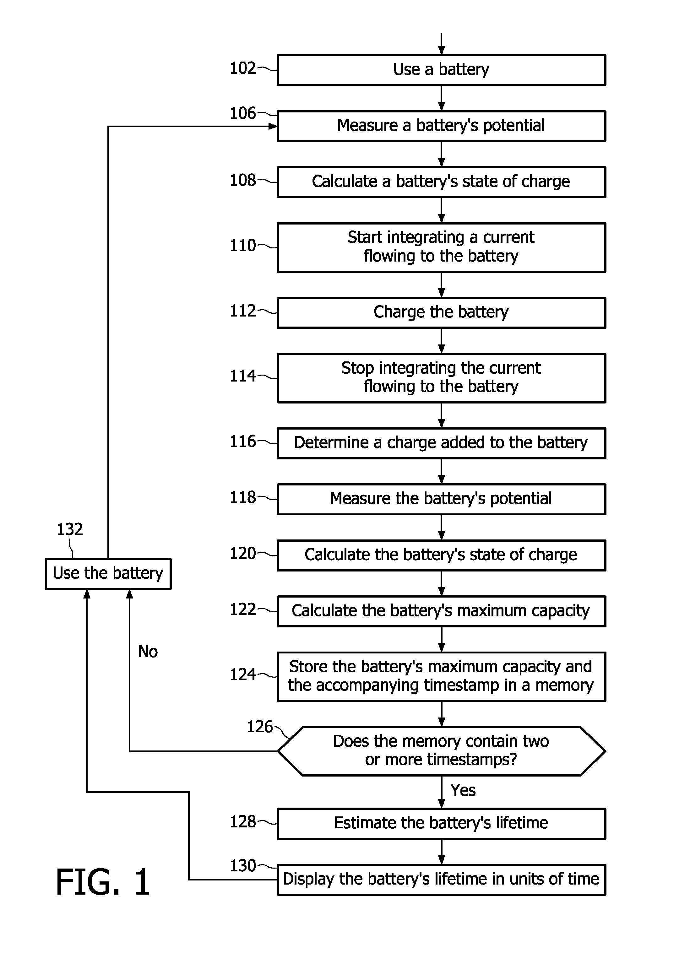
A method is disclosed for determining an end of life for a rechargeable battery comprising the steps of using the battery (102), charging the battery (112) and making an estimation of a battery's life-time (128), characterized by monitoring a battery characteristic indicative for battery aging (122).

Description

FIELD OF THE INVENTION[0001]The invention relates to a method for determining an end of life for a rechargeable battery comprising charging the battery and making an estimation of a battery's lifetime. The invention further relates to a device for determining an end of life for a rechargeable battery comprising a battery charger and a provision for estimation of a battery's lifetime.BACKGROUND OF THE INVENTION[0002]Techniques disclosed in WO-A 2006 / 094287 provide a method and a device for monitoring and storing data regarding the life history of a battery with which it is associated. A manufacturer's specified life expectancy measured in battery cycles is established for the battery under normal use and then the actual use of the battery is monitored and stored. Complete cycles, partial cycles and operation of the battery outside of acceptable specifications are automatically derived into a value in units equivalent to a number of battery cycles. This derivation is compared with the...

Claims


Application Information

Patent Timeline
Patent Type & Authority Applications(United States)
IPC IPC(8): G01R31/36H02J7/00
CPCG01R31/3679G01R31/392
Inventor MARTENS, HUBERT CECILE FRANCOIS
Owner KONINKLIJKE PHILIPS ELECTRONICS NV
Learn More