
Method for fracture surface extraction from microseismic events cloud

a cloud and microseismic technology, applied in the field of methods for modeling the surface of fractures, can solve the problems of large uncertainties in the inferred fracture dimension

Inactive Publication Date: 2011-02-03
SCHLUMBERGER TECH CORP
View PDF7 Cites 47 Cited by
  • Summary
  • Abstract
  • Description
  • Claims
  • Application Information

AI Technical Summary

Benefits of technology

The invention is a method for analyzing data related to subterranean formations using microseismic observations. The data is collected and analyzed using a tensor voting method to provide an estimate of the surface of the formation. This analysis can be used to tailor oil field services to the specific needs of the formation. The technical effect of this invention is to provide a more accurate and efficient way to analyze data related to subterranean formations, which can save time and money and improve the overall performance of oil field services.

Problems solved by technology

Human judgment is often relied upon to exclude isolated or sparse events in this exercise, leading to large uncertainties in the inferred fracture dimensions.
While manual extraction of the fracture shape from a microseismic cloud is possible, which is quite challenging and highly uncertain in itself, real time interpretation of microseismic events demands a robust and automated fracture extraction method.

Method used


Image

  • Method for fracture surface extraction from microseismic events cloud
  • Method for fracture surface extraction from microseismic events cloud
  • Method for fracture surface extraction from microseismic events cloud

Examples


example # 1

Example #1

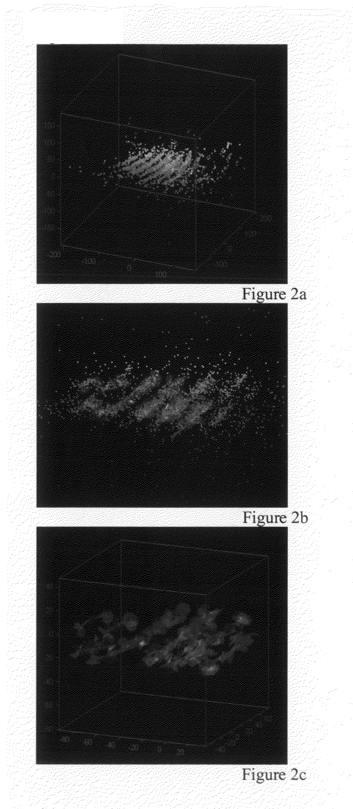
[0028]FIG. 2A shows the microseismic events cloud obtained during a hydraulic fracture treatment. FIG. 2B shows MS event cloud and extracted fracture surface, and FIG. (2C) shows only extracted fracture surface for data scaled by 5, and for small value of scaling parameter sigma (equal to 5). Because of values of scaling parameter, the extracted surface is more detailed and not planar. FIGS. 3A and 3B show the same microseismic event cloud but scaled with higher value of scaling parameter. It represents microseismic events cloud (FIG. 3A), MS event cloud and the extracted fracture surface (FIG. 3B), and extracted fracture surface (FIG. 3C) when MS data coordinates are scaled by 8. Because of larger scaling parameter, the extracted surface is more planar. These examples demonstrate the ability of tensor voting method to extract fracture surface features, and importance of data scaling for desired (more realistic) surface extraction. With the tensor voting method, the featur...

example # 2

Example #2

[0029]This is another example showing the original data cloud (FIG. 4A) in complex formation and the extracted fracture surfaces (FIG. 4B) with scale of voting field equal to 20. Using larger scale of voting field sigma allows to extract more planar fracture surface which fits well into the microsiesmic cloud of 21093 events (points). FIGS. 5A and 5B represent another angle of the same cloud of 21093 events (FIG. 5A), and extracted fracture surface (FIG. 5B).

example # 3

Example #3

[0030]FIGS. 6A and 6B illustrate Example 3. This example shows the original microseismic event cloud of 1633 events (FIG. 6A) in conventional (without natural fractures) reservoir and extracted planar fracture surface (FIG. 6B). For hydraulic fracturing in conventional reservoirs the expected generated fracture is a single planar fracture. This example demonstrates the ability of tensor voting methods to extract fracture surfaces in conventional reservoirs.


PUM


Abstract

Embodiments of this invention relate to a method for analysing data related to subterranean formations including collecting data from microseismic observations of a subterranean formation that is stored on a device, analysing the data using a tensor voting method, and providing an estimate of a surface of a subterranean formation. Embodiments of this invention relate to a method for analysing data related to subterranean formations including collecting data from microseismic observations of a subterranean formation, analysing the data using a tensor voting method, providing an estimate of a surface of a subterranean formation, and tailoring an aspect of an oil field service in response to the estimate.

Description

BACKGROUND[0001]1. Field[0002]This invention relates to methods to model a subterranean formation. In particular, the invention relates to methods for modeling surfaces of fractures within a subterranean formation.[0003]2. Description of the Related Art[0004]Hydraulic fracturing is one of the most widely used technologies for stimulating oil and gas production from a low permeability formation to increase hydrocarbon production. During a hydraulic fracture treatment, a fracturing fluid is injected at a pressure exceeding the in-situ stress of the target formation to create a large fracture. In a competent rock formation that does not contain extensive natural fractures, it is commonly believed that a single dominant fracture is created in the direction perpendicular to the minimum in-situ stress. The resulting fracture, filled with propping agent carried by the fluid, provides a highly conductive conduit to facilitate the flow of hydrocarbon into the wellbore.[0005]In recent years, ...

Claims


Application Information

Patent Timeline
Patent Type & Authority Applications(United States)
IPC IPC(8): G06F17/10G06G7/48
CPCG01V1/306
Inventor WENG, XIAOWEIKRESSE, OLGA
Owner SCHLUMBERGER TECH CORP
Learn More