
Rotary electric shaver

Inactive Publication Date: 2011-02-10
IZUMI PROD CO
View PDF16 Cites 29 Cited by
  • Summary
  • Abstract
  • Description
  • Claims
  • Application Information

AI Technical Summary

Benefits of technology

[0010]The present invention is created with the above-described considerations in mind, and it is an object of the present invention to provide a rotary electric shaver that reduces the amount of the flexion and the amount of extension / contraction of the universal joints that link the drive shafts to the inner cutters, so that the durability of the universal joints is improved and the production of abnormal sounds and noise is reduced.
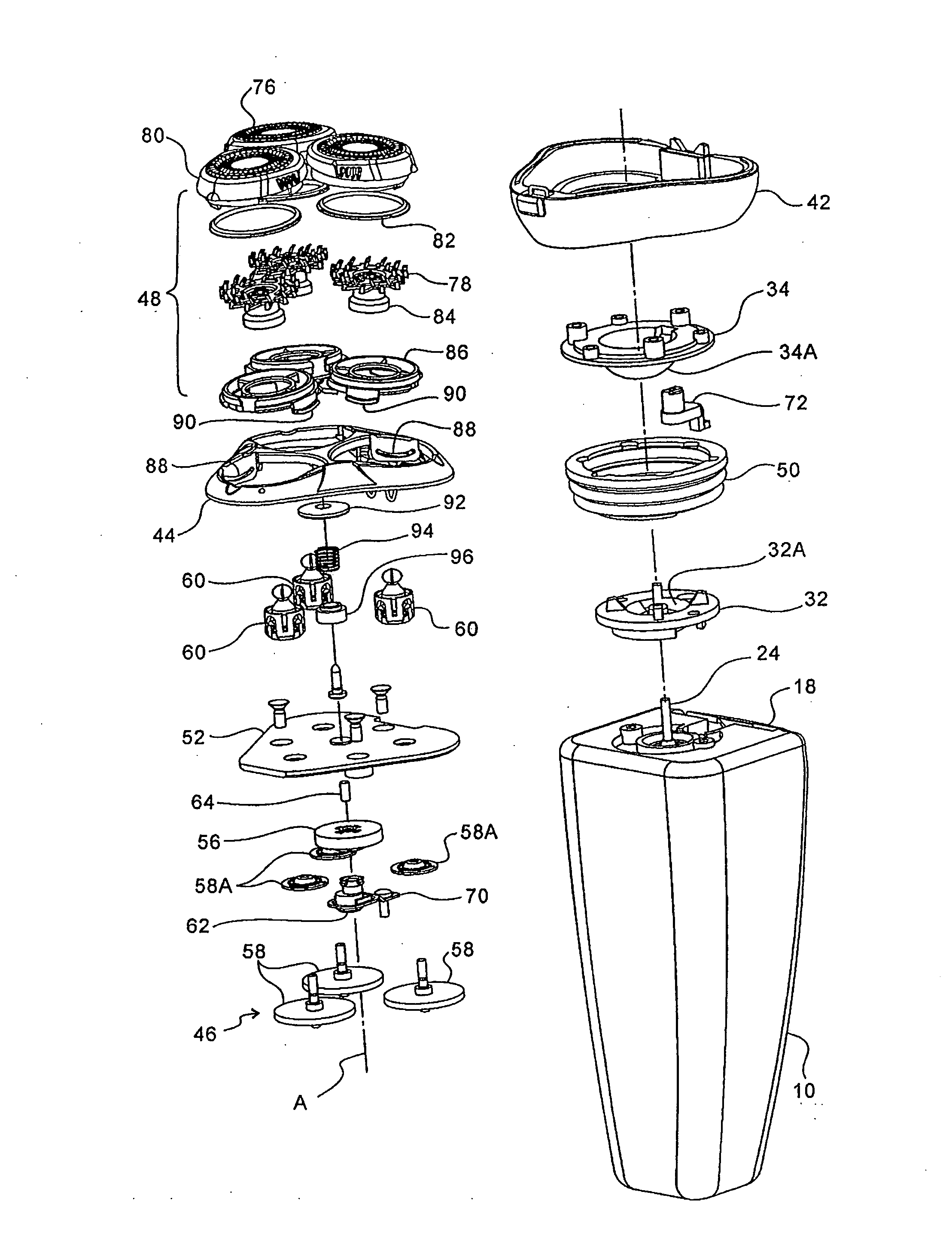
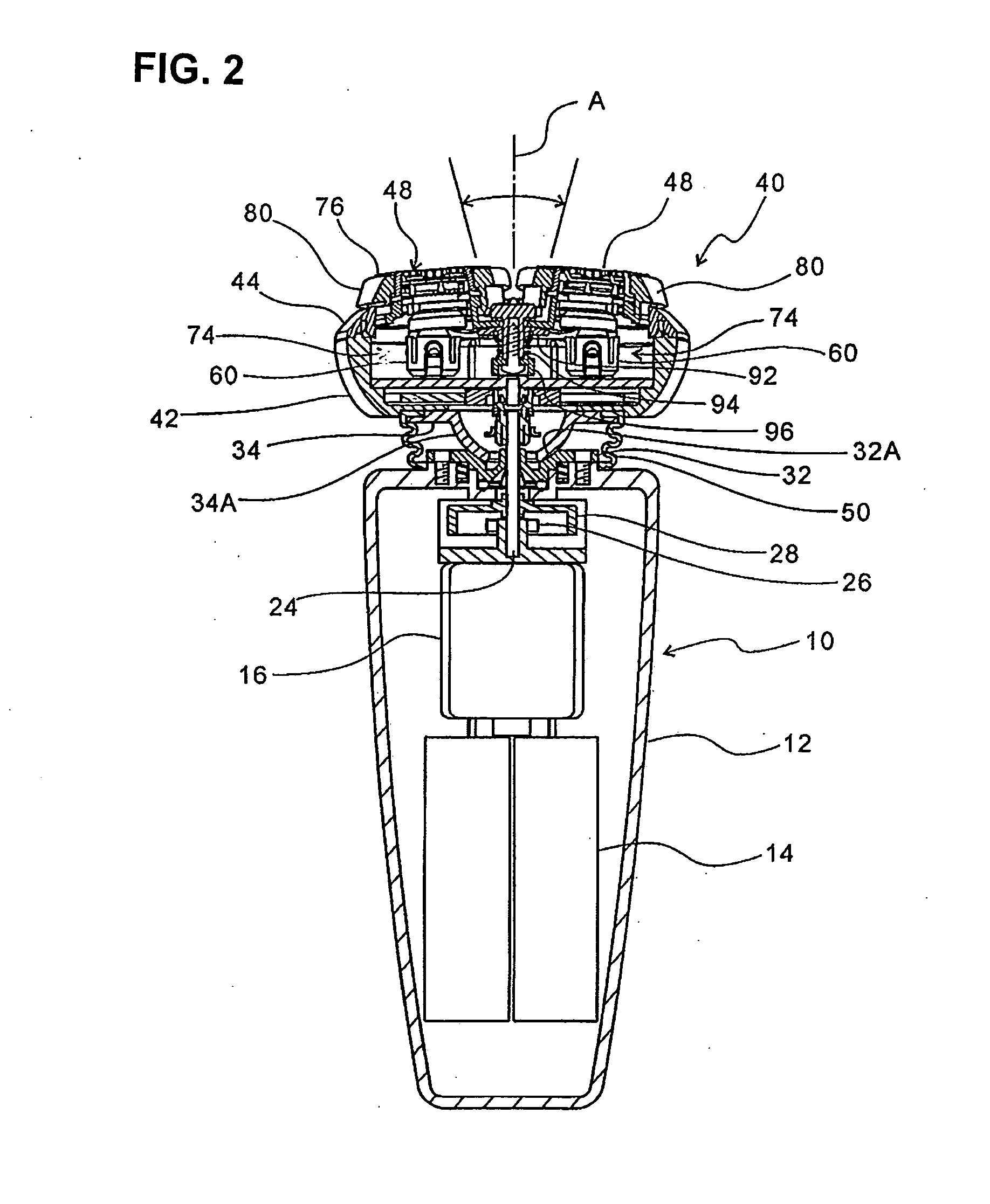
[0018]As seen from the above, in the present invention, the tilting of the outer cutters is divided into the pivotal motion of the shaver head relative to the shaver main body and the pivotal motion of the outer cutters relative to the shaver head (and, therefore, the outer cutter frame). Accordingly, the tilting of the outer cutters is absorbed by the respective flexion and extension / contraction of the first universal joint of the main drive shaft and by the second universal joints of the inner cutter drive shafts. The respective ranges of the flexion and extension / contraction of the first and second universal joints thus become smaller, and the loads applied to these universal joints can be reduced. As a result, the durability of the universal joints increases, and the production of abnormal sounds and noise is prevented. Furthermore, the shaving feel is improved because the outer cutters have increased range of mobility.
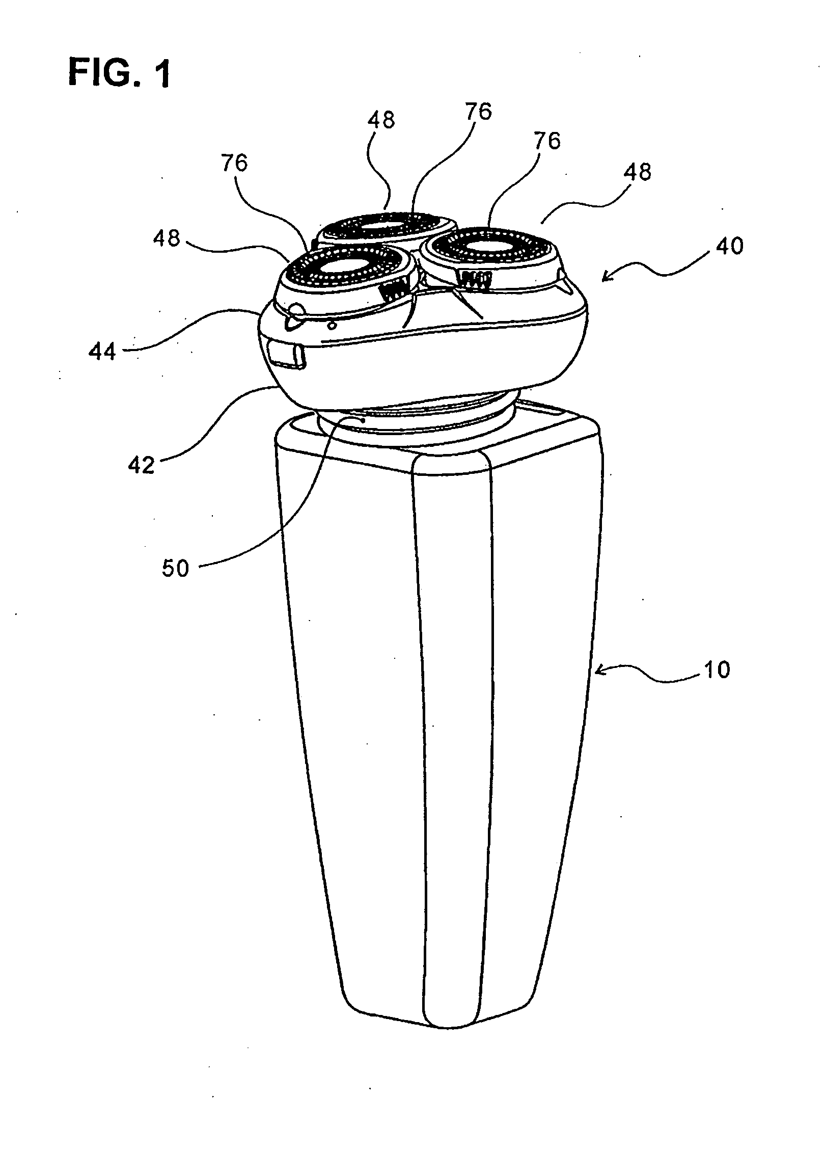
[0020]This junction between the shaver head and the shaver main body can be surrounded by a bellows-like boot which is adapted to resiliently pull the shaver head and the shaver main body toward each other. As a result, the number of parts can be reduced, and the construction is simplified.
[0022]The driving mechanism provided inside the shaver head can be comprised of a driving spur gear, which is formed integrally (including integrally molded or obtained by joining separate pieces) with the coupled-element on the output shaft side of the first universal joint, and a plurality of driven spur gears, which are securely attached to the inner cutter drive shafts of the cutter units and meshing with the driving spur gear. In this structure, the output shaft of the first universal joint can be formed integrally with the driving spur gear so as to reduce the thickness of the driving mechanism and as a result make it easier to accommodate it inside the shaver head, and the location of the driving spur gear is provided closer to the pivotal center of the shaver head so as to reduce the dimensions of the shaver head. In particular, by way of recessing the center of the lower face of the driving spur gear and allowing the pivotal center of the shaver head to enter in this recess, the dimensions of the shaver head can be further reduced.

Problems solved by technology

In such shavers, the range of mobility of the outer cutters is generally small, and thus the shaving surfaces of the outer cutters cannot be brought close enough to the skin and is limited in possible improvements in shaving feeling.
This leads to a decrease in the durability of the universal joints and contributes to the production of abnormal sounds and noise.

Method used


Image

  • Rotary electric shaver
  • Rotary electric shaver
  • Rotary electric shaver

Examples


Embodiment Construction

[0030]In FIGS. 1 to 4, the reference numeral 10 designates a shaver main body having a longitudinally elongated prismatic housing 12. Although this housing 12 is in fact formed by assembling members split apart by appropriate dividing surfaces (not shown), for the convenience of description, in FIGS. 2 and 3 the entire body is drawn as a unitary body.

[0031]Inside the housing 12, a rechargeable battery 14 is accommodated in the bottom portion, and an electric motor 16 is accommodated above the battery 14. As best seen in FIG. 3, a trimmer (trimming blade) 18 is mounted on the rear face of the housing 12 such that it can be opened by flipping it over backwards as shown by dotted line arrow around a pivot point 20. The reference numeral 22 designates an actuator used to raise and store the trimmer 18.

[0032]As shown in FIG. 3, the motor 16 is installed inside the housing 12 so that it is on the rear side of the housing. The rotary output shaft 16A of the motor 16 is oriented vertically ...


PUM


Abstract

A rotary electric shaver including cutter units, each having an outer cutter and an inner cutter rotating in resilient contact with the inner surface of the outer cutter, further including a shaver head which is pivotably provided on the shaver main body; an outer cutter frame attached to the shaver head to support the outer cutters in a depressible fashion; a main drive shaft for transmitting, via a first universal joint, the rotation of a motor housed in the shaver main body to a driving mechanism provided inside the shaver head; inner cutter drive shafts provided in the shaver head and rotationally driven by the driving mechanism; and second universal joints for transmitting the rotation of the inner cutter drive shafts to the inner cutters; and in this shaver the first universal joint being disposed near the pivotal center of the shaver head.

Description

BACKGROUND OF THE INVENTION[0001]1. Field of the Invention[0002]The present invention relates to a rotary electric shaver in which a plurality of cutter units including inner cutters rotating in sliding contact with the lower faces of outer cutters are provided on a shaver main body that houses a motor, etc.[0003]2. Description of the Related Art[0004]In one type of electric shaver, a plurality of outer cutters are provided in an outer cutter frame, which is securely attached to a shaver main body, so that the outer cutters are respectively allowed to make fine vertical (depressible) or pivotal motion (hereinafter simply and collectively called “vertical motion” as well) independently. In such shavers, the range of mobility of the outer cutters is generally small, and thus the shaving surfaces of the outer cutters cannot be brought close enough to the skin and is limited in possible improvements in shaving feeling.[0005]The inventor of the present application has previously proposed...

Claims


Application Information

Patent Timeline
IPC IPC(8): B26B19/14B26B19/38B26B19/28
CPCB26B19/14B26B19/145B26B19/146
Inventor SHIMIZU, TETSUHIKO
Owner IZUMI PROD CO
Learn More