Refrigerating apparatus

Active Publication Date: 2011-02-10
PHC HLDG CORP
View PDF1 Cites 28 Cited by
  • Summary
  • Abstract
  • Description
  • Claims
  • Application Information

AI Technical Summary

Benefits of technology

[0009]It is therefore the object of the present invention to accurately control the internal temperature while suppressing the number of activations of the compressors.

Problems solved by technology

However, in this case, since the number of activations of the compressors is increased there are drawbacks including not only the shortening of lives of electric components such as relays but also an increase in power consumption due to activation current.

Method used


Image

  • Refrigerating apparatus
  • Refrigerating apparatus
  • Refrigerating apparatus

Examples


first embodiment

=Configuration of Refrigerating Apparatus=

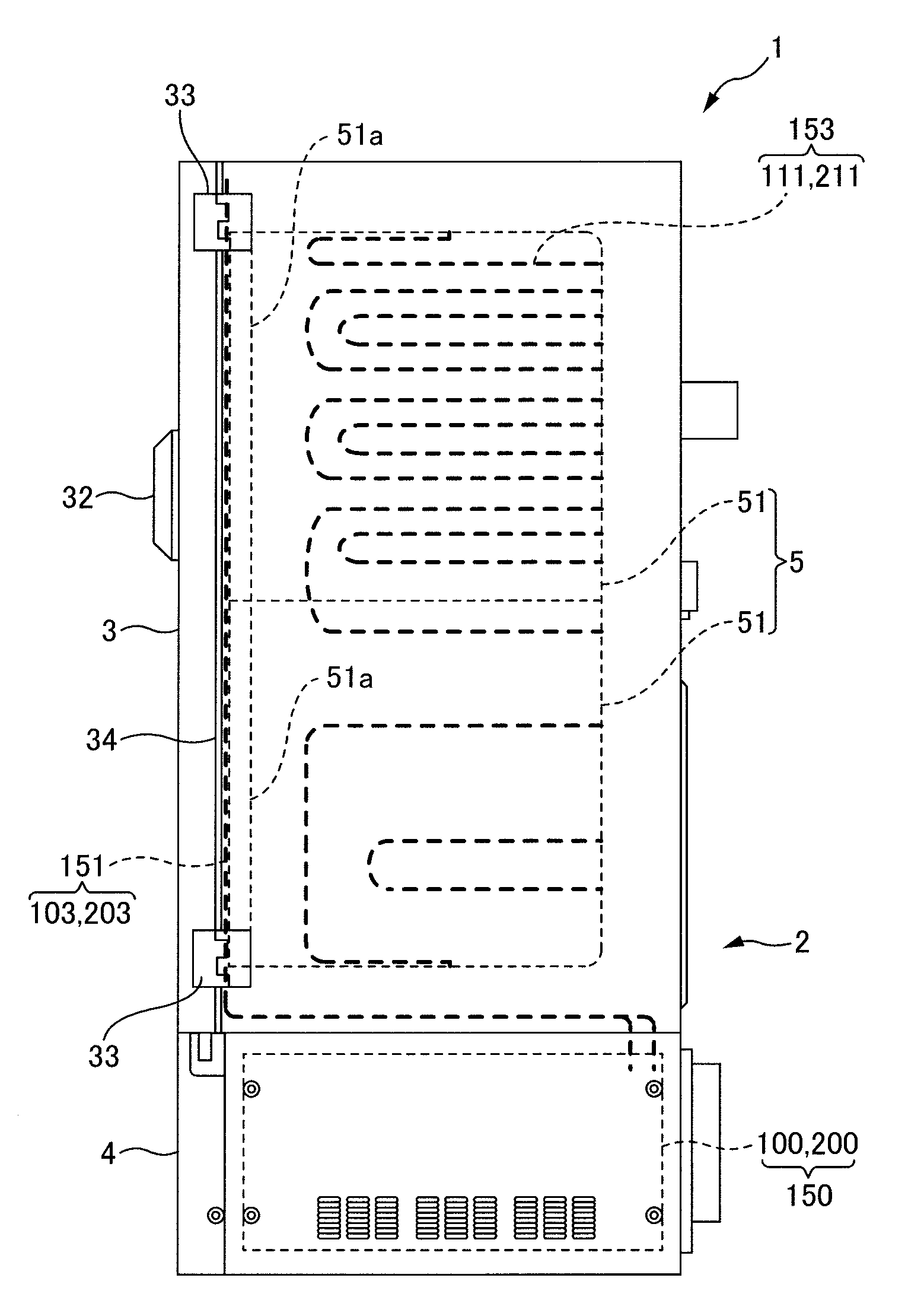
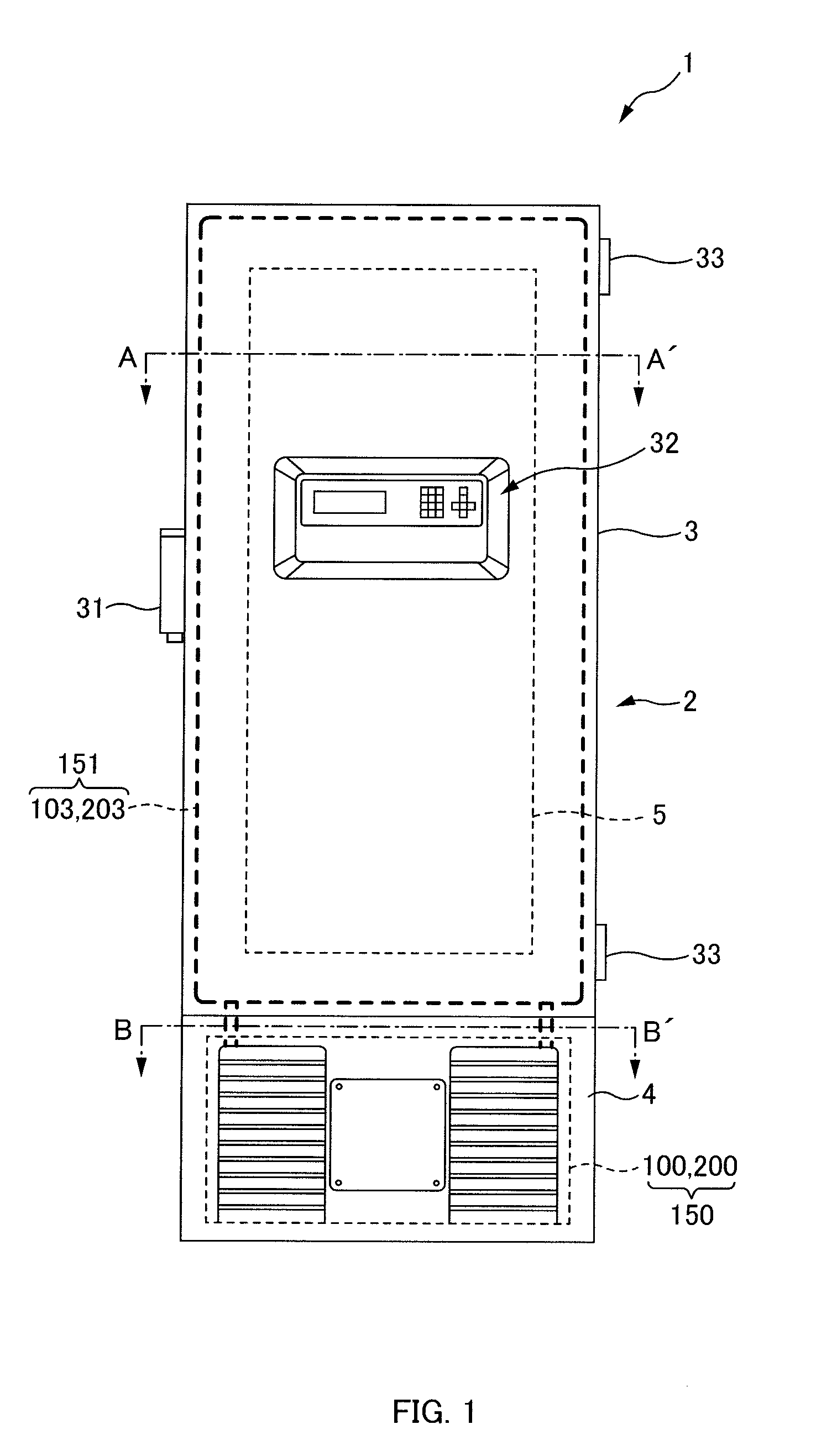
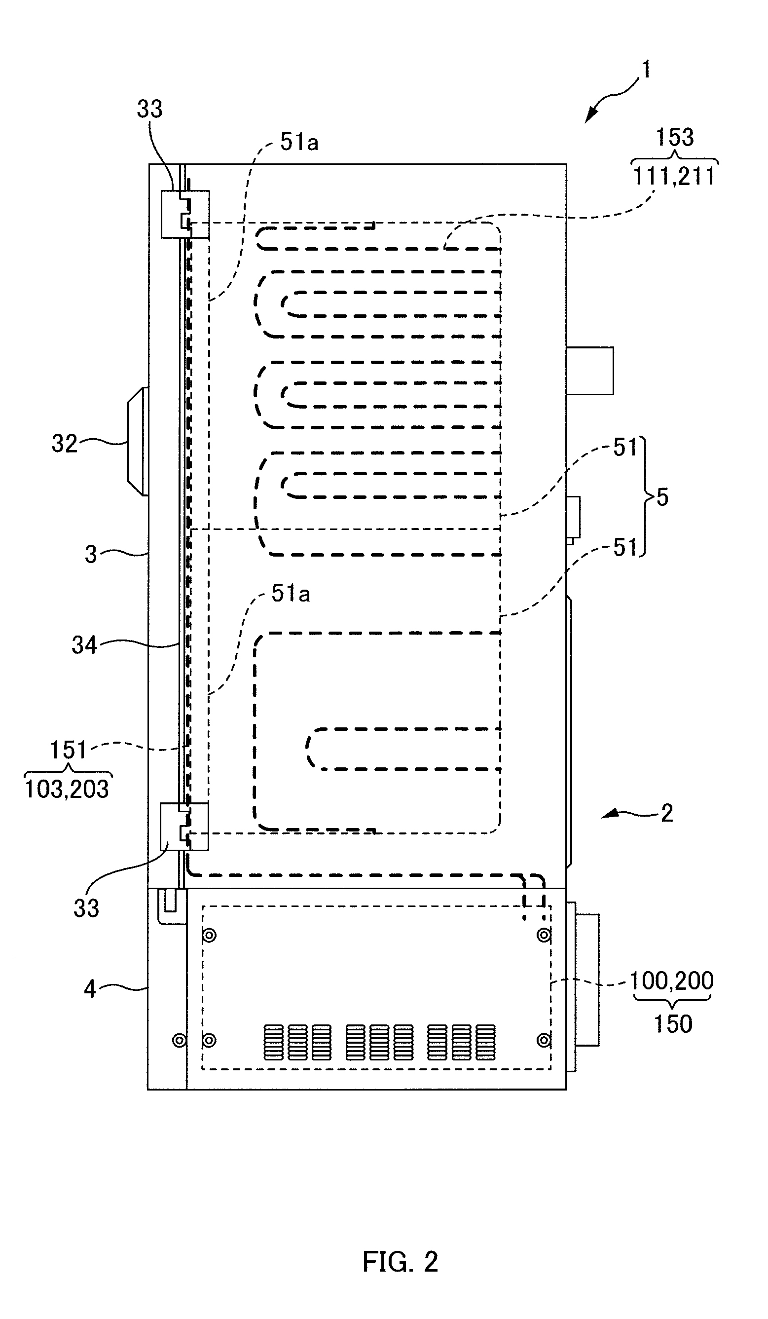
[0032]An exemplary configuration of a refrigerating apparatus 1 of a first embodiment will be described with reference to FIGS. 1 to 4.

[0033]FIG. 1 is a front view of an example of the refrigerating apparatus 1 of the first embodiment. FIG. 2 is a side view of the refrigerating apparatus 1 of FIG. 1. FIG. 3 is a circuit diagram of an example of a first refrigerant circuit 100 and a second refrigerant circuit 200 of the first embodiment. FIG. 4 is a block diagram of an example of a control circuit 300 responsible for controlling the first refrigerant circuit 100 and the second refrigerant circuit 200 of the first embodiment.

[0034]As depicted in FIGS. 1 to 4, the refrigerating apparatus 1 includes two substantially the same refrigerant circuits (the first refrigerant circuit 100 and the second refrigerant circuit 200), a temperature sensor 307 that detects an internal temperature, a microcomputer (a first control device, a second control devic...

second embodiment

[0124]A refrigerating apparatus is known that includes two refrigerant circuits having compressors, condensers, pressure reducers, and evaporators.

[0125]Since the refrigerant is compressed, condensed and then evaporated in each of the two refrigerant circuits, an object to be cooled that is, for example, in thermal contact with the two evaporators in common is refrigerated.

[0126]Such a refrigerating apparatus includes fans configured to cool each of the condensers to facilitate the heat exchange in the respective condensers of the two refrigerant circuits. In other words, the two condensers included in the two refrigerant circuits are respectively and individually cooled by the two fans.

[0127]In the above refrigerating apparatus, in a case where one of the two fans stops due to a failure of a fan motor, a heat exchange amount between refrigerant and air is decreased in the condenser corresponding to this fan. Therefore, a condensation amount of the refrigerant is decreased in the co...

third embodiment

[0169]A refrigerating apparatus is known that includes two refrigerant circuits having compressors, condensers, pressure reducers, and evaporators. In each of the two refrigerant circuits, the refrigerant discharged from the compressor is cooled and liquefied by the condenser and, via the pressure reducer, evaporated by the evaporator, and thus, for example, an internal portion of a cold storage cabinet in thermal contact with the two evaporators in common is cooled.

[0170]This refrigerating apparatus includes fans configured to facilitate the cooling of the refrigerant for the respective condensers of the two refrigerant circuits. The two respective fans individually blow air to the two condensers included in the two refrigerant circuits to facilitate the heat exchange between the ambient air and the refrigerant.

[0171]Since the role of the fans is important for the heat exchange of the condenser as above, the refrigerating apparatus always monitors whether a fan motor that rotates e...


PUM


Abstract

A refrigerating apparatus includes first and second refrigerant circuits including respective first and second compressors, condensers, pressure reducers, and evaporators, connected circularly with first and second refrigerant pipes, respectively, refrigerants discharged from the first and second compressors being respectively condensed at the first and second condensers and thereafter respectively evaporated at the first and second evaporators to acquire a cooling effect; a temperature sensor that detects a temperature of an internal portion of a cold storage cabinet, the first and second evaporators being disposed to cool the internal portion simultaneously; and a first control device that controls the first and second compressors such that both of them are operated each time a temperature detected by the temperature sensor reaches a first temperature, and the first and second compressors are alternately operated each time a temperature detected by the temperature sensor reaches a second temperature lower than the first temperature.

Description

CROSS-REFERENCE TO RELATED APPLICATIONS[0001]This is a continuation application of International Patent Application No. PCT / JP2009 / 66275 filed Sep. 17, 2009, which claims the benefit of priority to Japanese Patent Application No. 2008-243064 filed Sep. 22, 2008. The full contents of the International Patent Application are incorporated herein by reference.BACKGROUND OF THE INVENTION[0002]1. Field of the Invention[0003]The present invention relates to a refrigerating apparatus.[0004]2. Description of the Related Art[0005]A refrigerating apparatus is known that includes two refrigerant circuits having compressors, condensers, pressure reducers, and evaporators (see, e.g., Japanese Patent Application Laid-Open Publication No. 2005-90917). Since the refrigerant discharged from the compressor in each of the two refrigerant circuits is cooled and liquefied by the condenser and evaporated by the evaporator after the depressurization by the pressure reducer, for example, an internal portion...

Claims


Application Information

Patent Timeline
IPC IPC(8): F25D17/06F25D17/00F25B41/00
CPCF25B49/027F25B2400/06F25B2600/111F25D11/04F25D21/04F25B49/022F25D2400/14F25D2400/361Y02B30/743Y02B40/32F25D29/00F25D19/04Y02B30/70Y02B40/00F25B49/02F25B1/10F25B7/00
Inventor SHINYA, HIDETOSHIKOBAYASHI, SUSUMUOKUDA, SATOSHITSURUMA, RYUICHITAMAOKI, YUICHITOBE, RYUZO
Owner PHC HLDG CORP
Why Eureka
Try Eureka