Lower die for press bending and tool using the same

a technology of press bending and dies, which is applied in the direction of manufacturing tools, shaping tools, forging/hammering/pressing machines, etc., can solve the problem that the end of the vertical side interferes with the body of the bending machin

Inactive Publication Date: 2011-02-10
MAKINO OSAMU
View PDF11 Cites 6 Cited by
  • Summary
  • Abstract
  • Description
  • Claims
  • Application Information

AI Technical Summary

Benefits of technology

[0012]With the configurations described above, the bending tool of the invention has the following effects.(1) When the upper die and the lower die are brought together with the metal sheet placed on the lower die, the blade edge of the upper die enters the process groove of the rotating block while bending the metal sheet and the rotating block is rotated forward. The L-shaped work is inclined forward at the bending point together with the rotating block which is inclined forward of the bending machine. The front side of the L-shaped work is moved upward by an angle smaller than 45 degrees with respect to the horizontal plane at the front side of the bending machine. Thus the amount of upward movement of the metal sheet during the bending operation can be controlled to the minimum. With this configuration, the operator can stay safe.(2) For the manufacture of the U-shaped metal piece, the U-shaped metal piece is also inclined forward together with the rotating block which is inclined forward of the bending machine at the bending point (which corresponds to the second bending point 7b described above). Thus the front side of the base of the U-shaped metal piece is moved upward by an angle smaller than 45 degrees with respect to the horizontal plane at the front side of the bending machine. The reversed angle of the vertical side of the U-shaped metal piece is much smaller than 45 degrees. The vertical side extends in the direction much closer to the plumb line. It rarely happens that the end of the vertical side interferes with the body of the bending machine even if the vertical side is long. Accordingly, a U-shaped metal piece of increased depth can be manufactured through bending.

Problems solved by technology

It rarely happens that the end of the vertical side interferes with the body of the bending machine even if the vertical side is long.

Method used


Image

  • Lower die for press bending and tool using the same
  • Lower die for press bending and tool using the same
  • Lower die for press bending and tool using the same

Examples


Embodiment Construction

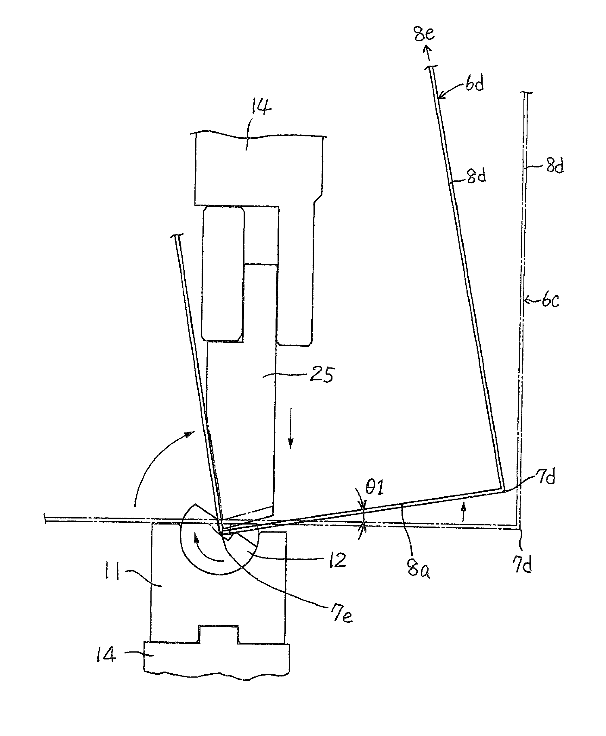
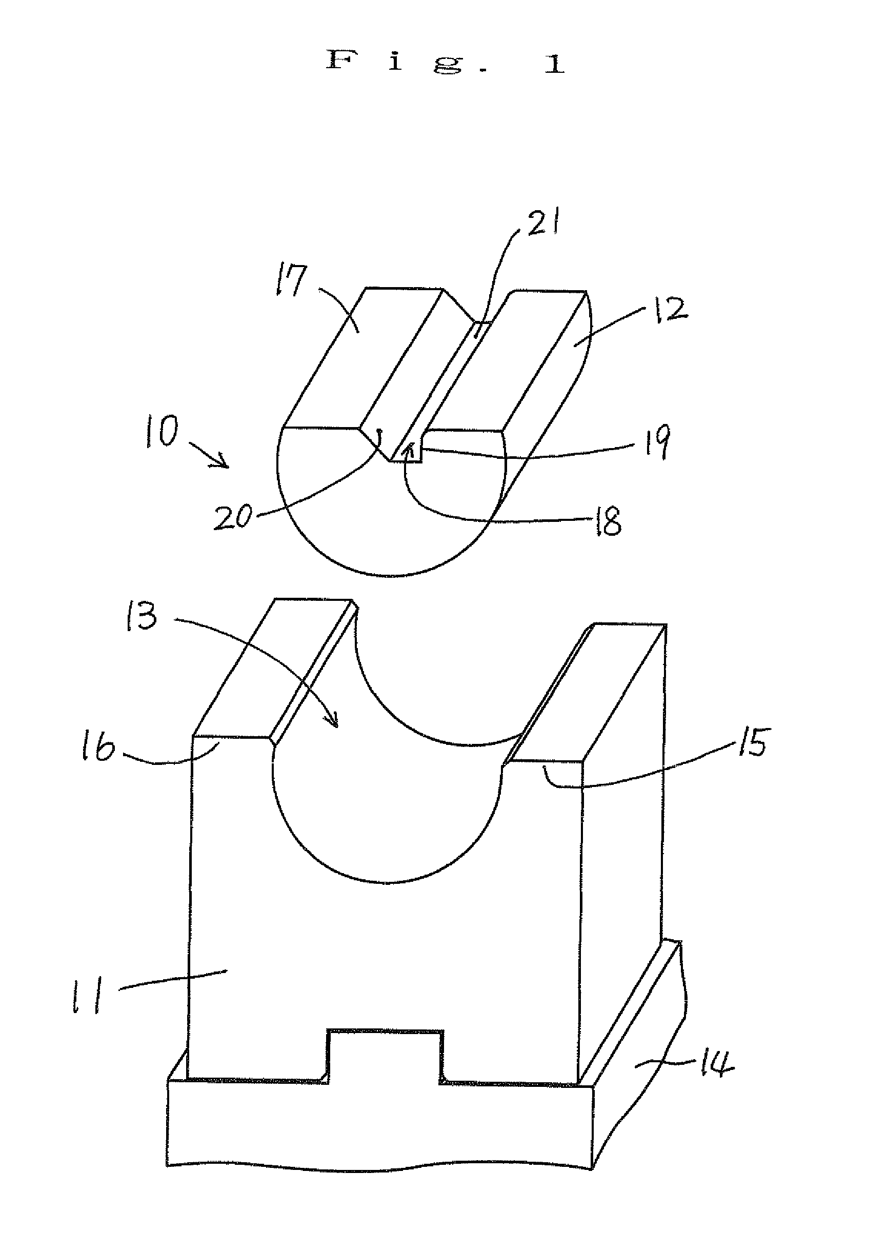
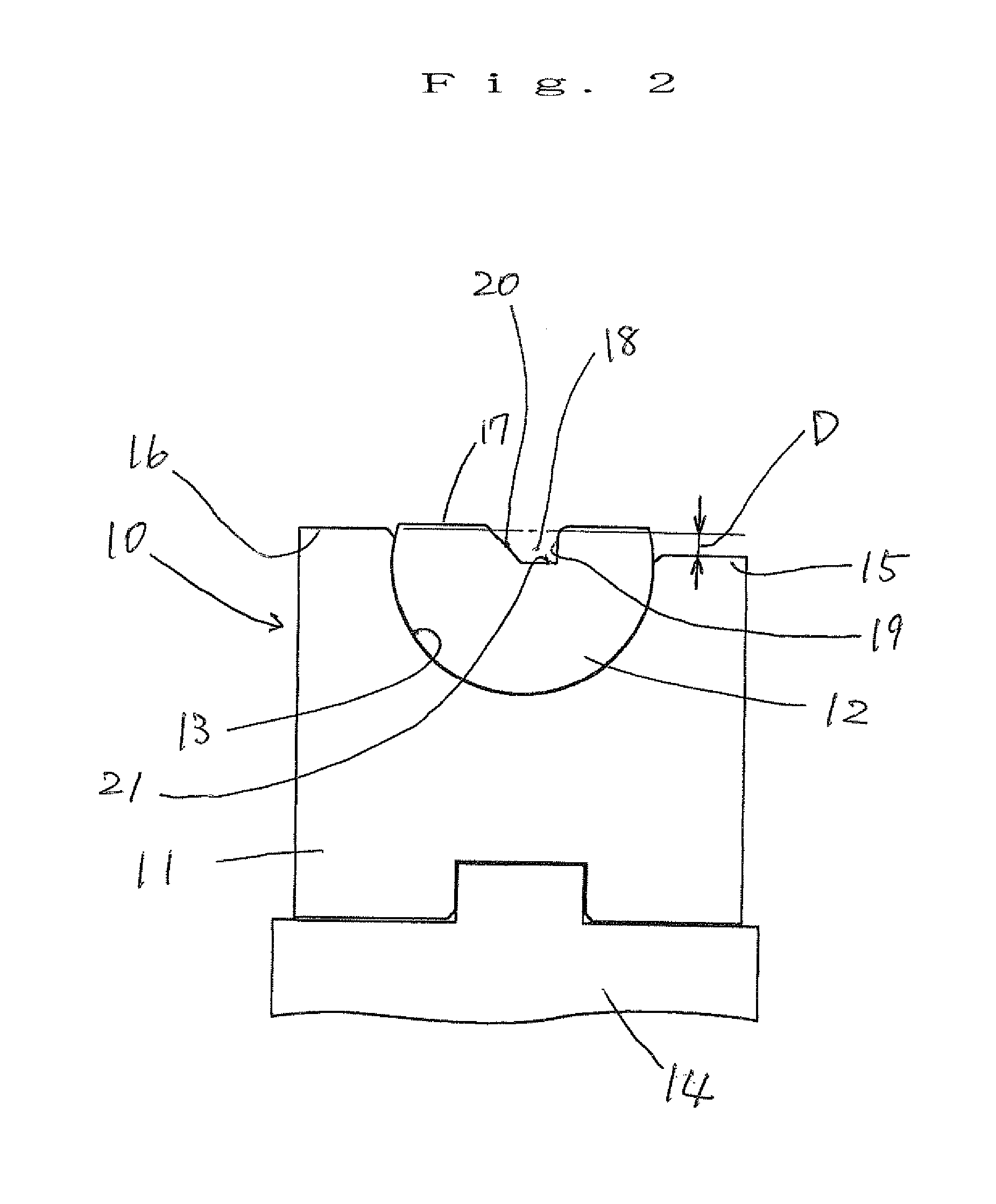
[0022]Hereinafter, a first embodiment of the invention will be described with reference to the drawings. FIG. 1 is an exploded perspective view of a lower die of a tool for press bending according to the first embodiment of the invention and FIG. 2 is a left side view thereof. As illustrated in FIGS. 1 and 2, the lower die 10 comprises a block body 11 and a rotating block 12. On an upper surface of the block body 11, a groove 13 is formed to extend in a right and left direction. The block body 11 is fixed to a bending machine 14. The block body 11 includes a front shoulder 15 and a rear shoulder 16 at the front and rear sides of the groove 13. The front shoulder 15 is smaller in height than the rear shoulder 16. This means that a level difference D is defined between the front shoulder 15 and the rear shoulder 16 such that the front shoulder 15 is lower than the rear shoulder 16. The groove 13 is formed as a hollow cylinder with a semicircular cross section. Preferably, the rotating...


PUM

PropertyMeasurementUnit
angleaaaaaaaaaa
angleaaaaaaaaaa
reversed angleaaaaaaaaaa

Abstract

In order to achieve a bending operation which provides a U-shaped metal piece of increased depth and to provide a bending operation safe to an operator involved in the bending operation, the invention is a lower die for press bending which includes: a block body which includes a groove on an upper surface thereof, the groove extending in a right and left direction, and the block body being fixed to a bending machine; and a rotating block which is received by the groove of the block body and is capable of oscillating about an axis of the groove, wherein a process groove is formed on an upper surface of the rotating block to receive a blade edge of an upper die. The block body includes a front shoulder and a rear shoulder at the front and rear sides of the groove. A level difference is defined between these shoulders such that the front shoulder is smaller in height than the rear shoulder.

Description

BACKGROUND OF THE INVENTION[0001]1. Field of the Invention[0002]The present invention relates to a tool for press bending (hereinafter, referred to as a “bending tool”) mounted on a press bending machine (or a “press brake”) which is a bending apparatus for bending mechanical parts, such as metal plates. More particularly, the invention relates to a lower die of the bending tool.[0003]2. Description of the Related Art[0004]Many L-shaped or U-shaped metal pieces are manufactured as brackets or reinforcing members of various machines or devices. A related art bending tool for manufacturing such L-shaped or U-shaped metal pieces and operation states thereof are described in JP-B-58-41927 and illustrated in FIG. 9 of the present application.[0005]FIG. 9 illustrates the manufacture of an ordinary L-shaped metal piece. With this unit, an L-shaped bending tool (i.e., a die) 2 and a V-block 3 are disposed opposite to each other along a vertical direction. The die 2 corresponds to an upper d...

Claims


Application Information

Patent Timeline
Patent Type & Authority Applications(United States)
IPC IPC(8): B21D7/04B21D5/00
CPCB21D5/0209
Inventor MAKINO, OSAMU
Owner MAKINO OSAMU
Why Eureka
Try Eureka