
Compound archery crossbow

Inactive Publication Date: 2011-02-10
DARLINGTON REX FRLIN
View PDF6 Cites 51 Cited by
  • Summary
  • Abstract
  • Description
  • Claims
  • Application Information

AI Technical Summary

Benefits of technology

[0015]In another embodiment, the cams are reversed in orientation with the bowstring positioned horizontally between cams and the riser so the power stroke can be increased, which results in better performance.

Problems solved by technology

But, with two-groove cams, the cams can get out of sync when the bowstring is drawn back to cock the bow, which can offset the nock travel so it is no longer straight with the barrel, thereby causing the arrow to launch incorrectly.
Latching the bowstring off center from the correct nocking point when cocking the bow can also cause erratic arrow flight.
Accordingly, a continuous problem with compound bows is the inherently unequal application of force to opposite sides of the mounting axles of the pulleys and / or cams as the bowstring is drawn.
Moreover, placing the power cables all on one cam creates more load on one side of the limb.
A yoke system, however, is not effective to balance the load on the limbs with a front mounted (i.e., reverse draw) bowstring because it is not possible to draw the bowstring past the split in the cables because they are anchored at the axle on each side of the pulleys and / or cams.
And, anchoring the power cables to the limb still affects the timing of the cams and causes problematic twisting of the limbs.
In addition, riggings that position all of the power cables on one side of the bowstring can generate cable forces on one side of the pulley or cam, which results in a design that tends to lean, tip, or twist the limbs of a bow with respect to the plane of the bowstring, thereby causing an arrow to launch incorrectly.
The power cables, however, must still be deflected to move them out of the path of the bowstring and an arrow, which will still cause some twisting of the limbs.

Method used


Image

  • Compound archery crossbow
  • Compound archery crossbow
  • Compound archery crossbow

Examples


Embodiment Construction

[0037]Certain terminology is used herein for convenience only and is not to be taken as a limitation on the present invention. The terminology includes the words specifically mentioned, derivatives thereof, and words of similar import. The embodiments discussed herein are not intended to be exhaustive or to limit the invention to the precise form disclosed. Those embodiments are chosen and described to best explain the principles of the invention and its application and practical use and to enable others skilled in the art to best utilize the invention.

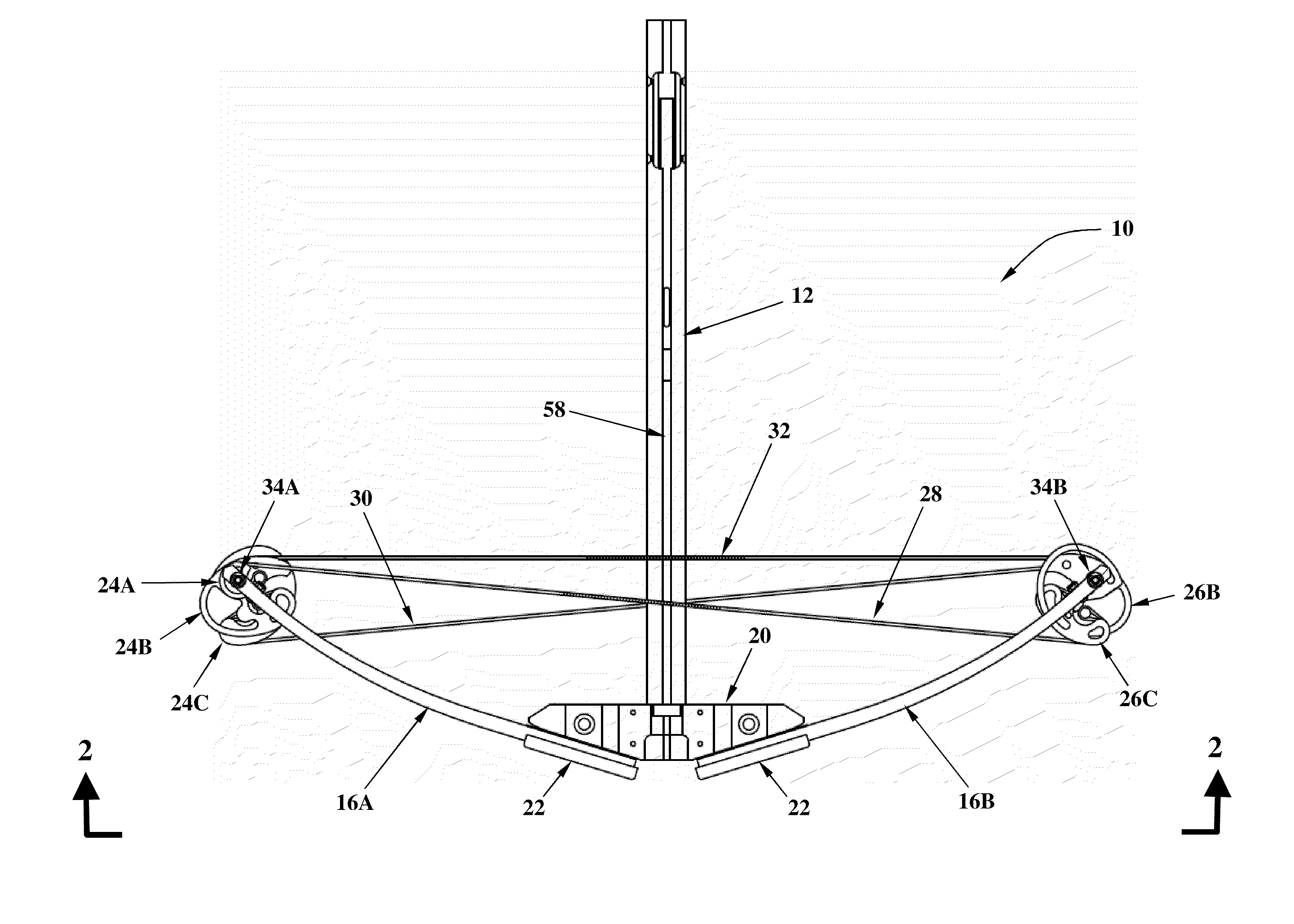
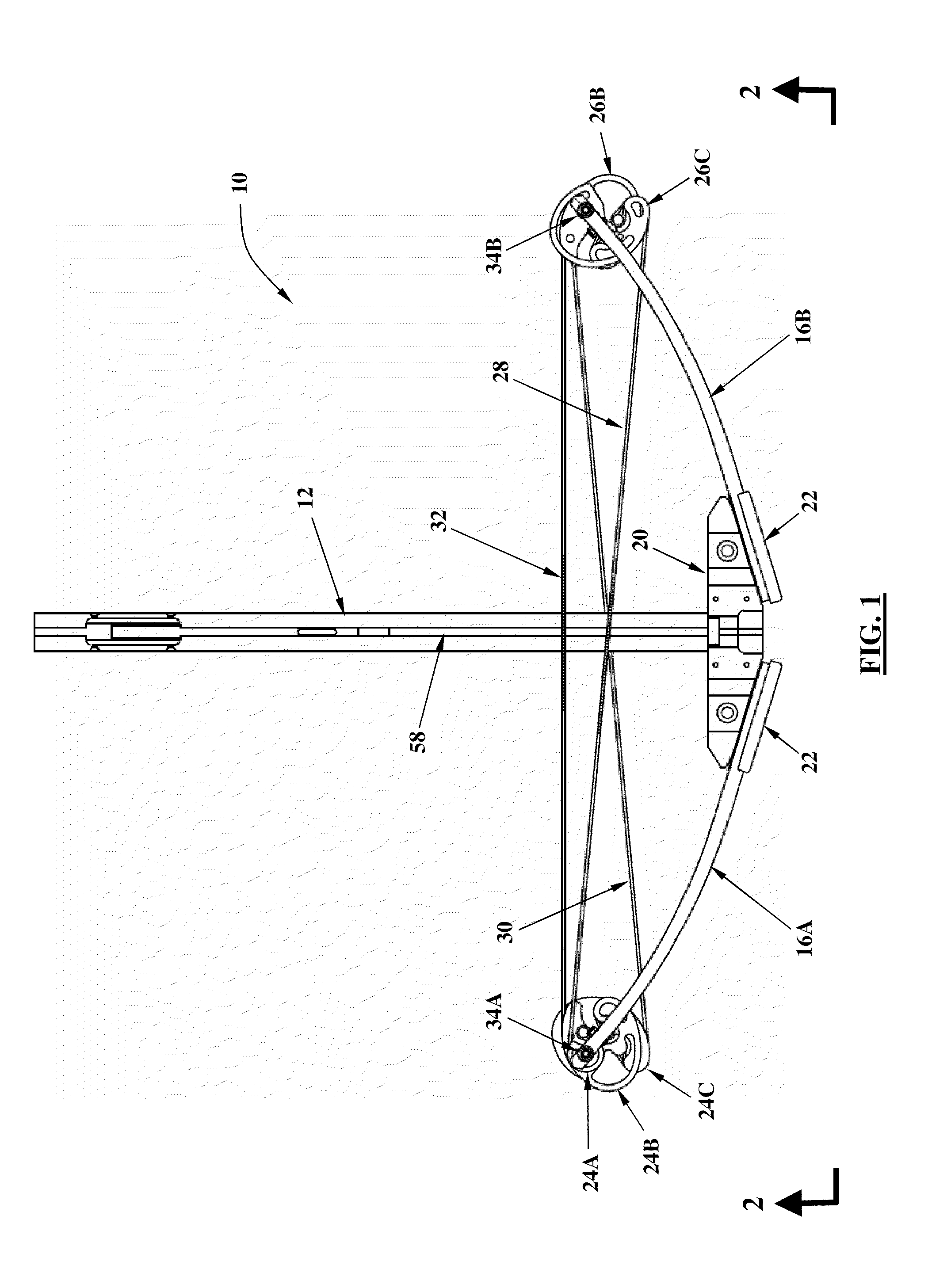
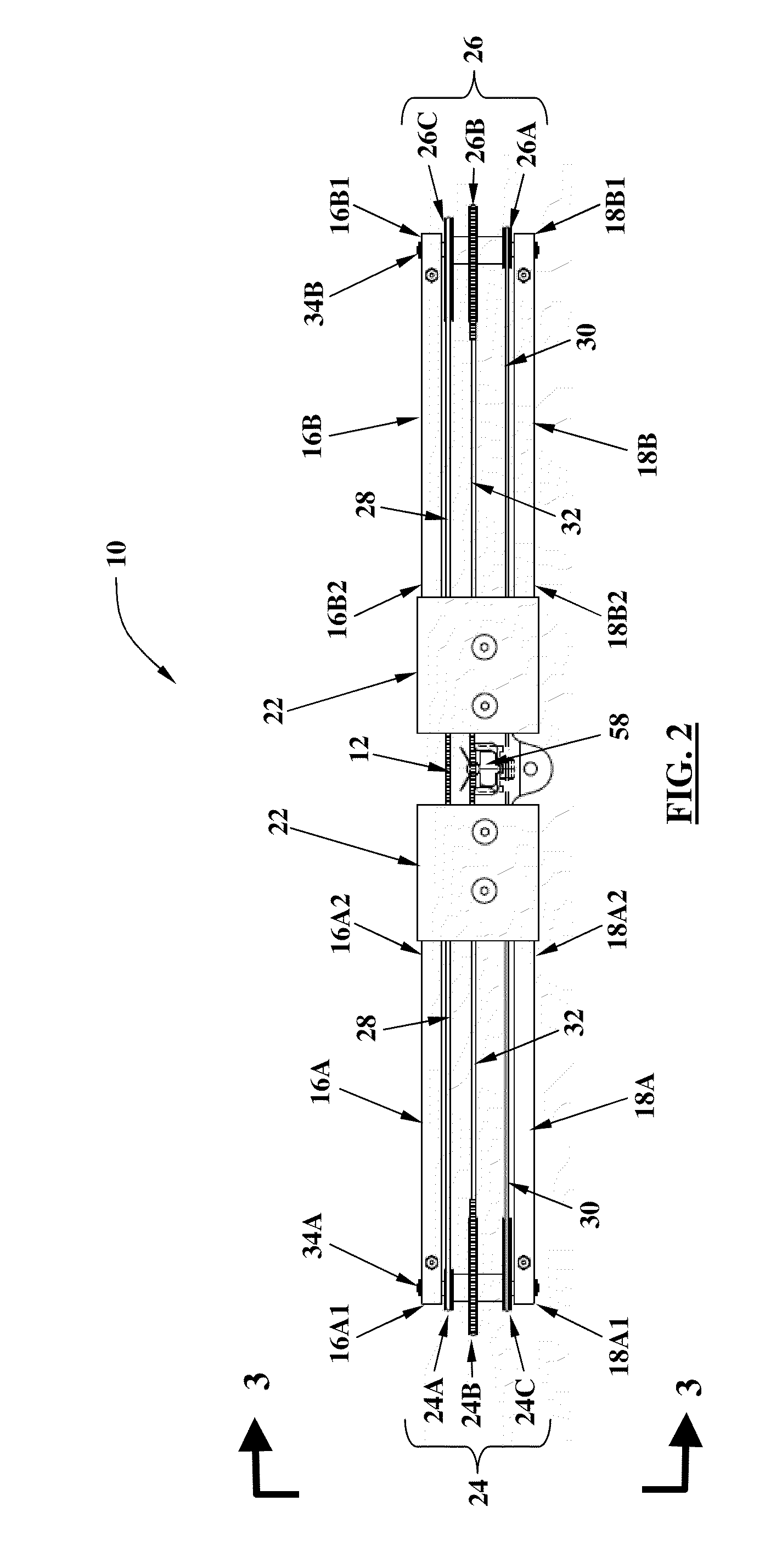
[0038]Referring now to the drawings, FIGS. 1-3 illustrate a first embodiment of the present invention directed to a compound archery crossbow 10 that may have a barrel 12 supported by a stock 14. The crossbow 10 may include an upper pair 16A & B and a lower pair 18A & B of limbs, wherein the upper pair of limbs 16A & B has a first member 16A with a distal end 16A1 and a proximal end 16A2 and a second member 16B with a distal end 16B1 ...


PUM


Abstract

The invention is directed to a compound archery crossbow wherein the power cables and the bowstring remain substantially parallel allowing the bowstring to be positioned for increased power and accuracy of an arrow and / or wherein the power stroke has been extended by positioning the bowstring farther from the string catch.

Description

FIELD OF THE INVENTION[0001]This invention relates to an improved compound archery crossbow.BACKGROUND OF THE INVENTION[0002]Crossbows conventionally include an elongated barrel of wood, metal or composite composition that forms a mounting base for the remainder of the crossbow hardware. A pair of resilient limbs of wood, steel, aluminum, and / or composite composition project in opposite directions from one end of the barrel, with the free ends of the limbs being joined by a bowstring cable. A support is provided on the upper surface of the barrel for holding an arrow. A trigger mechanism is carried by the barrel for engaging, and holding the bowstring cable in the drawn or cocked position, and for selectively releasing the cable so as to propel the bolt from the bow.[0003]Conventional dual-cam compound crossbows have a power cam mounted at the end of each of the two bow limbs to control the draw force on the bowstring and the bending of the limbs as the bowstring is drawn back to co...

Claims


Application Information

Patent Timeline
IPC IPC(8): F41B5/12F41B5/10
CPCF41B5/123F41B5/105
Inventor DARLINGTON, REX FRANKLIN
Owner DARLINGTON REX FRLIN
Learn More