Method of assisting piloting, piloting assistance means, and a piloting assistance device for a rotorcraft using said piloting assistance means to implement said piloting assistance method

a technology of rotorcraft and piloting assistance, which is applied in the direction of rotocraft, propellers, position/direction control, etc., can solve the problems of reducing the flight control structure of the rotorcraft, reducing the flight control efficiency of the rotorcraft, and reducing the weight of the rotorcraft. , to achieve the effect of reducing the weight of the rotorcraft and simplifying the flight control structur

Active Publication Date: 2011-02-10
EUROCOPTER
View PDF5 Cites 42 Cited by
  • Summary
  • Abstract
  • Description
  • Claims
  • Application Information

AI Technical Summary

Benefits of technology

It should be observed that autopilot means may control the piloting assistance means to cause them to perform the functions of existing dampers and parallel actuators.
The device of the invention thus limits the elements needed for assisting the pilot, thereby optimizing the weight of the device.

Problems solved by technology

Consequently, the main rotor does indeed provide the rotorcraft with lift.
The linkages are thus generally very long and heavy, particularly the yaw control linkage.
The members of the linkages give rise to friction forces that may be considerable for linkages of great length.
Under such conditions the pilot may have difficulty in moving the cyclic stick or the collective pitch lever, given the amount of force required.
Nevertheless, that first solution is difficult to implement, in particular on existing rotorcraft.
Nevertheless, such assistance systems are bulky and heavy.
Furthermore, they run the risk of hydraulic or pneumatic leakage, leading to a loss of effectiveness.
Finally, the gas in pneumatic assistance systems is sensitive to variations in temperature, unfortunately all too frequent in aviation, in particular because of operating at different altitudes, and the fluids used in hydraulic assistance systems possess polluting chemical compounds.
Thus, the series actuators are generally very fast, but with little authority in amplitude.
Such a device is necessarily bulky, heavy, and expensive.

Method used


Image

  • Method of assisting piloting, piloting assistance means, and a piloting assistance device for a rotorcraft using said piloting assistance means to implement said piloting assistance method
  • Method of assisting piloting, piloting assistance means, and a piloting assistance device for a rotorcraft using said piloting assistance means to implement said piloting assistance method
  • Method of assisting piloting, piloting assistance means, and a piloting assistance device for a rotorcraft using said piloting assistance means to implement said piloting assistance method

Examples


Embodiment Construction

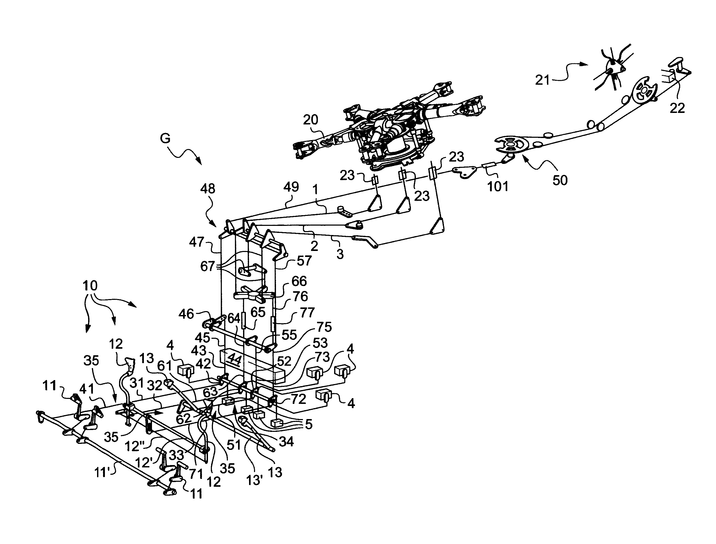
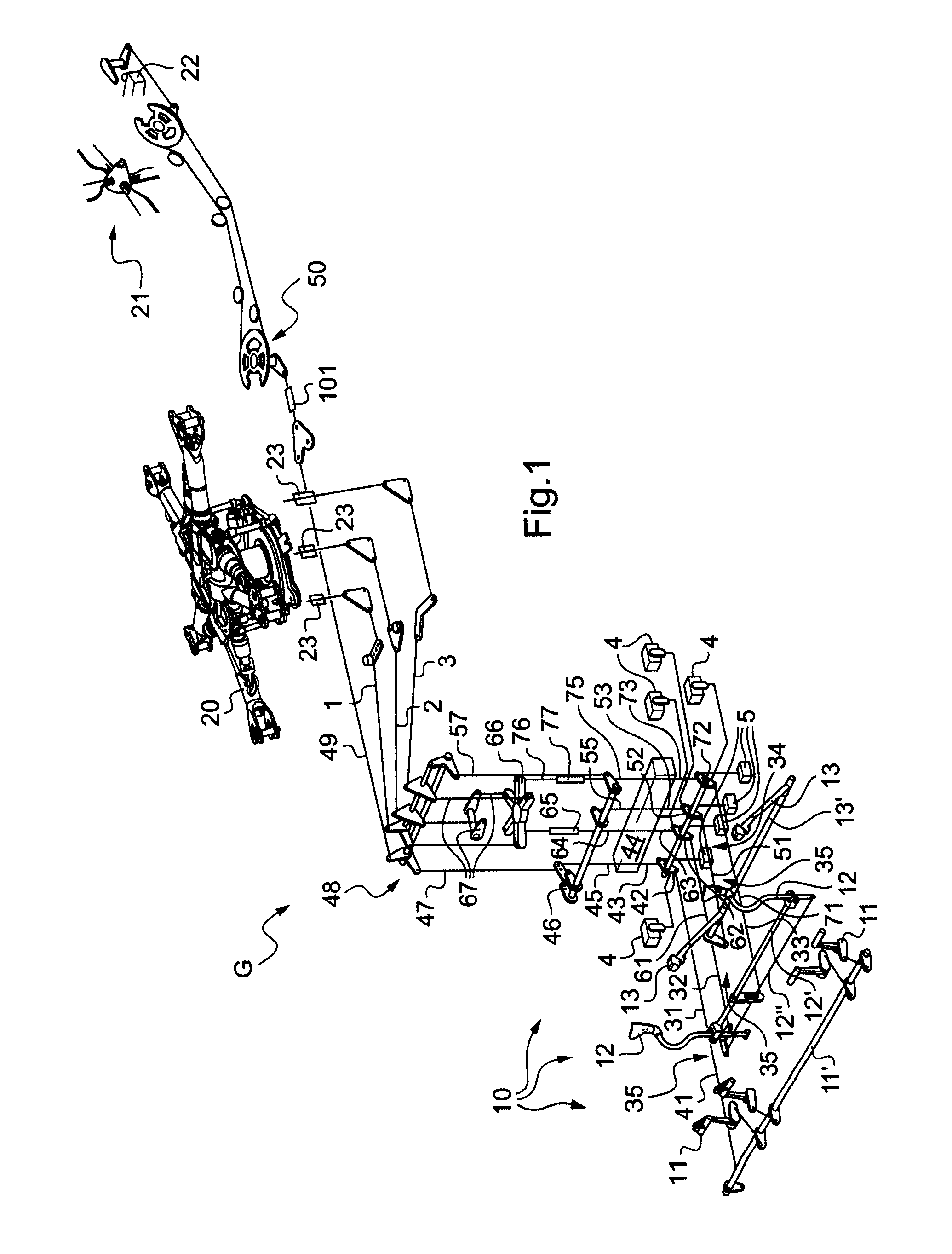
FIG. 1 is a view of a rotorcraft G having a prior art piloting assistance device.

The rotorcraft G has flight controls 10 connected to the main lift and advance rotor 20 and to the tail rotor 21 by linkages 35. In particular, the flight controls 10 comprise two sets of rudder pedals 11 for acting on the pitch of the blades of the tail rotor 21, together with two cyclic sticks 12 and two collective pitch levers 13 for modifying the pitch of the blades of the main lift rotor 20 and the pitch of the blades of the tail rotor 21.

In order to control the rotorcraft G in yaw, the rudder pedals 11 are connected together by a yaw jackshaft 11′ controlling a servo-control 22 for modifying the pitch of the blades of the tail rotor 21 via a yaw linkage 31 that comprises in succession:a bottom first rod 41;crank means 42;a second rod 43;a hydraulic block 44;a third rod 45;collective pitch and yaw coupling means 46;a fourth rod 47;a mixer 48;a fifth rod 49; anda control system 50 having a control c...


PUM


Abstract

The present invention relates to a device and method of assisting the piloting of a rotorcraft, the rotorcraft having a flight control (10) for controlling a rotor (20, 21) via at least one linkage (35), during which method an additional force is generated by at least one piloting assistance means (100) mechanically linked to the linkage (35), the additional force being a function of the position of the flight control (10) and of an instantaneous force as measured on the linkage (35).

Description

CROSS REFERENCE TO RELATED APPLICATIONThis application claims the benefit of FR 0902913 dated Jun. 16, 2009, the disclosure of which is incorporated herein by reference.FIELD OF THE INVENTIONThe present invention relates to a method of assisting the piloting of a rotorcraft, and in particular a helicopter.BACKGROUND OF THE INVENTIONConventionally, a rotorcraft commonly includes a main lift rotor provided with a plurality of blades.The blades of the main lift rotor describe a very flat cone having a plane of rotation that is perpendicular to the general lift generated by said main rotor. This general lift of the main rotor may then be resolved into a vertical lift force proper and a horizontal force that serves to cause the helicopter to move in translation. Consequently, the main rotor does indeed provide the rotorcraft with lift.In addition, on a helicopter, by controlling the shape and the tilt of said cone relative to the frame of reference of the helicopter, a pilot can control ...

Claims


Application Information

Patent Timeline
Patent Type & Authority Applications(United States)
IPC IPC(8): B64C27/00
CPCB64C27/68B64C27/56
Inventor ALLIETA, JEAN-MARIECHADUC, BRUNOLAFISSE, JEAN-FRANCOISHONNORAT, OLIVIER
Owner EUROCOPTER
Why Eureka
Try Eureka