Hardware fastening structure for computer

Inactive Publication Date: 2011-02-10
BLOOMBER FINANCE LP +1
View PDF11 Cites 13 Cited by
  • Summary
  • Abstract
  • Description
  • Claims
  • Application Information

AI Technical Summary

Problems solved by technology

Generally, the hard disk drives and the CD-ROM drives are stacked on each other, and are fixed by a

Method used


Image

  • Hardware fastening structure for computer
  • Hardware fastening structure for computer
  • Hardware fastening structure for computer

Examples


Embodiment Construction

[0011]Embodiments of the present hardware fastening structure 100 will be now described in detail with reference to the drawings.

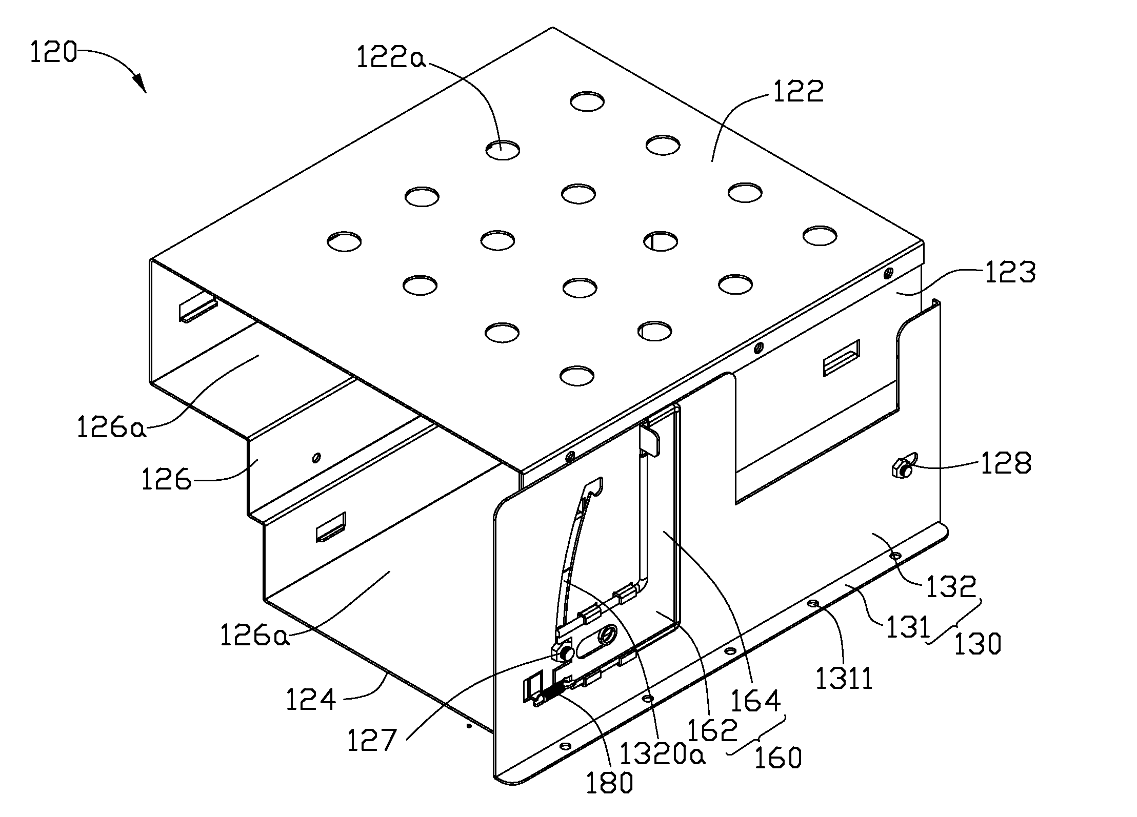
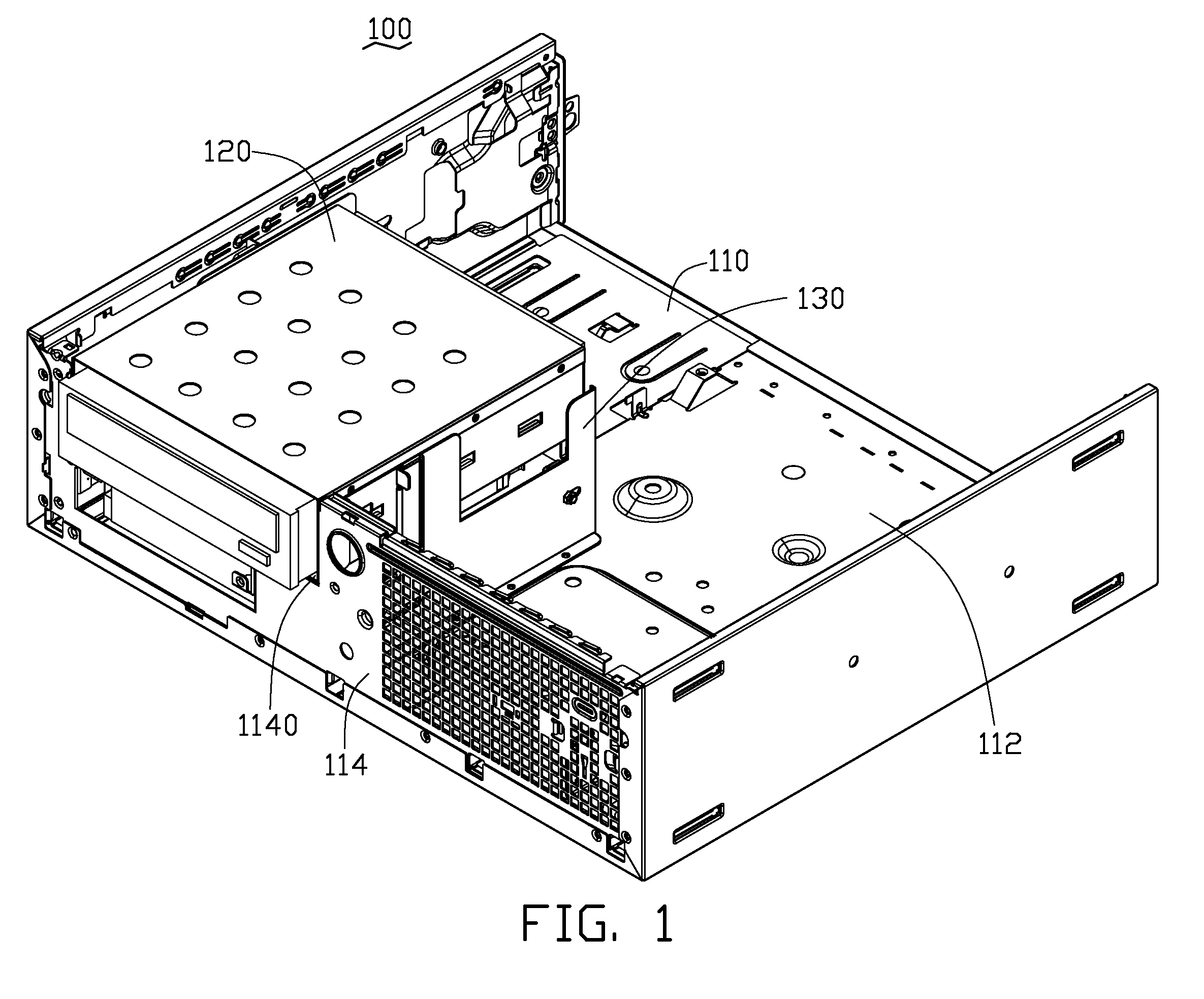
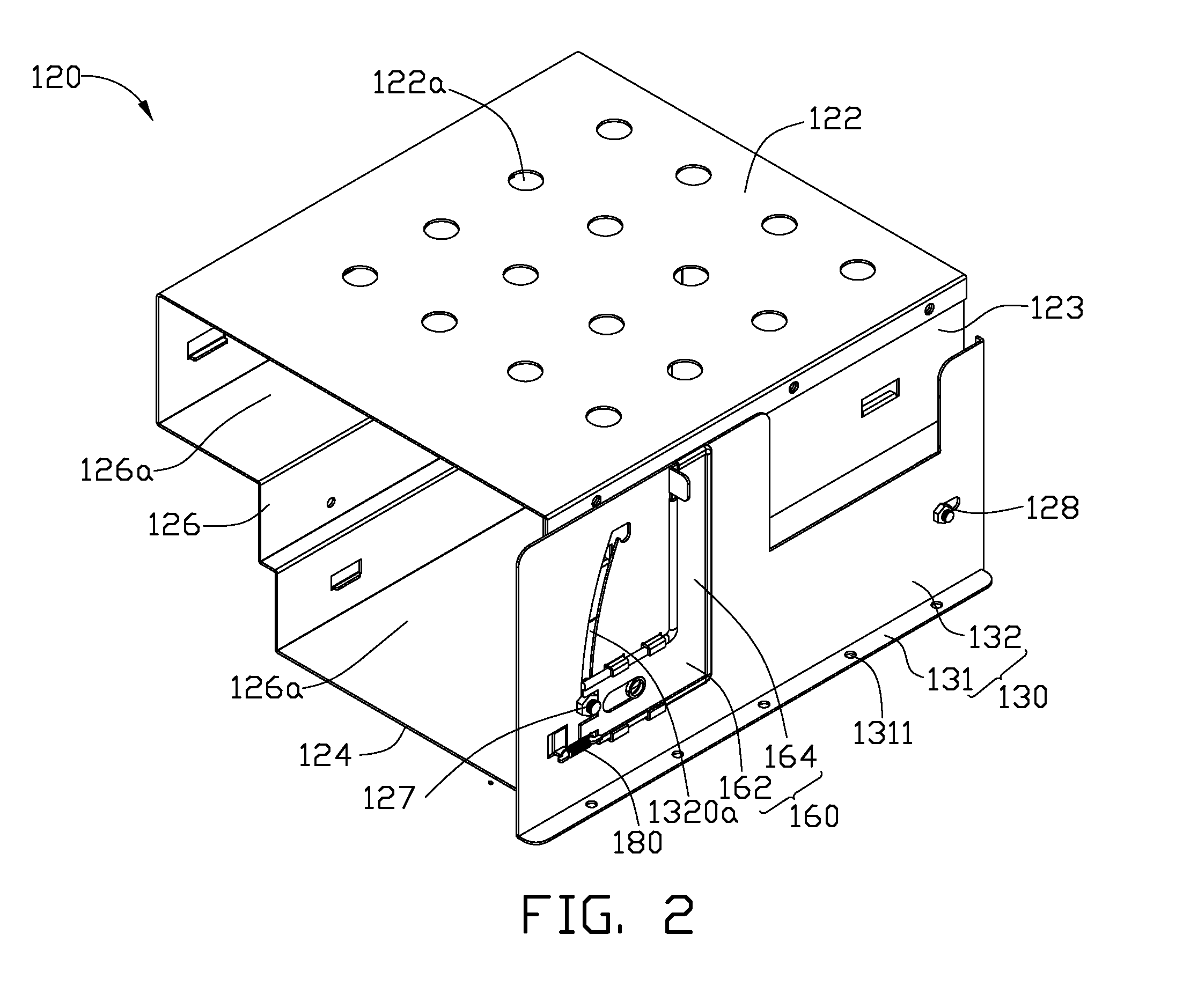
[0012]Referring to FIGS. 1-3, a hardware fastening structure 100 according to an exemplary embodiment, is shown. The hardware fastening structure 100 includes a housing 110 of a computer, a bracket 120, a fixed frame 130, and a locking plate 160. The fixed frame 130 is fixed to the inside of the housing 110, and the bracket 120 is rotatably connected to the fixed frame 130. A CD-ROM drive 140 and a hard disk drive 150, as exemplary devices, are fixedly received in the bracket 120. The bracket 120 can be lifted relative to the fixed frame 130, and therefore to be lifted from the housing 110 to take out the CD-ROM drive 140 and the hard disk drive 150 from the bracket 120 or reload the CD-ROM drive 140 and the hard disk drive 150 into the bracket 120.

[0013]The housing 110 is a protective shell for receiving a series of different electrical elements of the co...


PUM


Abstract

A hardware fastening structure for fastening hardware for computer includes a housing, a bracket, and a fixed frame. The housing includes a bottom plate. The bracket includes a first side-board. A first bolt is extended outward from and substantially perpendicular to the first side-board. The fixed frame includes a bottom board is positioned onto the bottom plate of the housing, and a back board substantially perpendicular to and adjacent to the bottom board. The back board defines a cambered guiding slot. The cambered guiding slot includes an arced sliding portion and a locating portion communicating with the sliding portion. The locating portion is above the sliding portion. The first bolt is inserted through the sliding portion, and is capable of sliding along the sliding portion until the first bolt is locked in locating portion to lift the bracket relative to the housing.

Description

BACKGROUND[0001]1. Technical Field[0002]The disclosure relates to hardware fastening structures for use in computers to stably hold and support a hard disk drive, a CD-ROM drive and so on.[0003]2. Description of the Related Art[0004]Hard disk drives and CD-ROM drives are very important components in computers for storing and accessing data. They must be stably mounted inside the housings of the computers to provide a stable work environment and correspondingly prolonging their lifespans. Generally, the hard disk drives and the CD-ROM drives are stacked on each other, and are fixed by a number of fasteners, resulting in time-consuming and difficult assembling and repairing processes.[0005]Therefore, what is needed is to provide a hardware fastening structure which can overcome the disadvantage above mentioned.BRIEF DESCRIPTION OF THE DRAWINGS[0006]Many aspects of the present hardware fastening structure could be better understood with reference to the accompanying drawings. The compo...

Claims


Application Information

Patent Timeline
IPC IPC(8): H05K7/14
CPCG06F1/187Y10S248/918G11B33/128G11B33/124
Inventor CHANG, CHIN-MING
Owner BLOOMBER FINANCE LP
Why Eureka
Try Eureka