Digital Phase-Locked Loop Clock System

a phase-locked loop and clock system technology, applied in the direction of pulse automatic control, vehicle components, electrical equipment, etc., can solve the problems of increasing the cost and complexity of the clock system, occupying additional space for extra components, and unable to manufacture filters easily

Active Publication Date: 2011-02-10
ANALOG DEVICES INC
View PDF10 Cites 75 Cited by
  • Summary
  • Abstract
  • Description
  • Claims
  • Application Information

AI Technical Summary

Problems solved by technology

The filter cannot easily be fabricated within the integrated circuit in which the DPLL is fabricated, and therefore, it is provided as a...

Method used


Image

  • Digital Phase-Locked Loop Clock System
  • Digital Phase-Locked Loop Clock System
  • Digital Phase-Locked Loop Clock System

Examples


Embodiment Construction

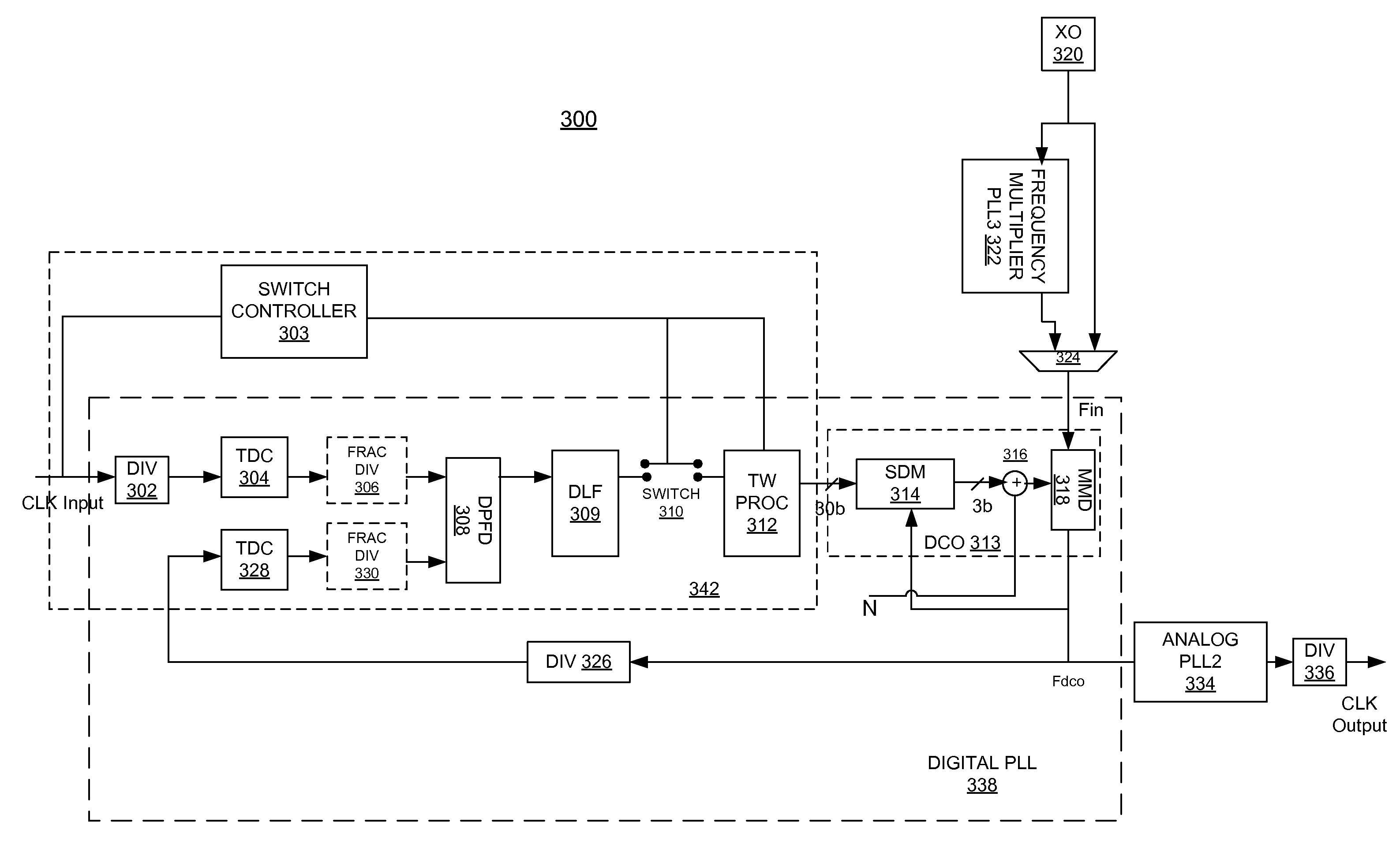
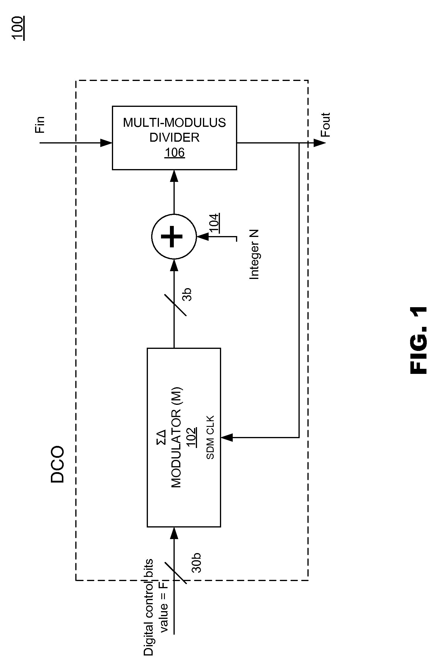
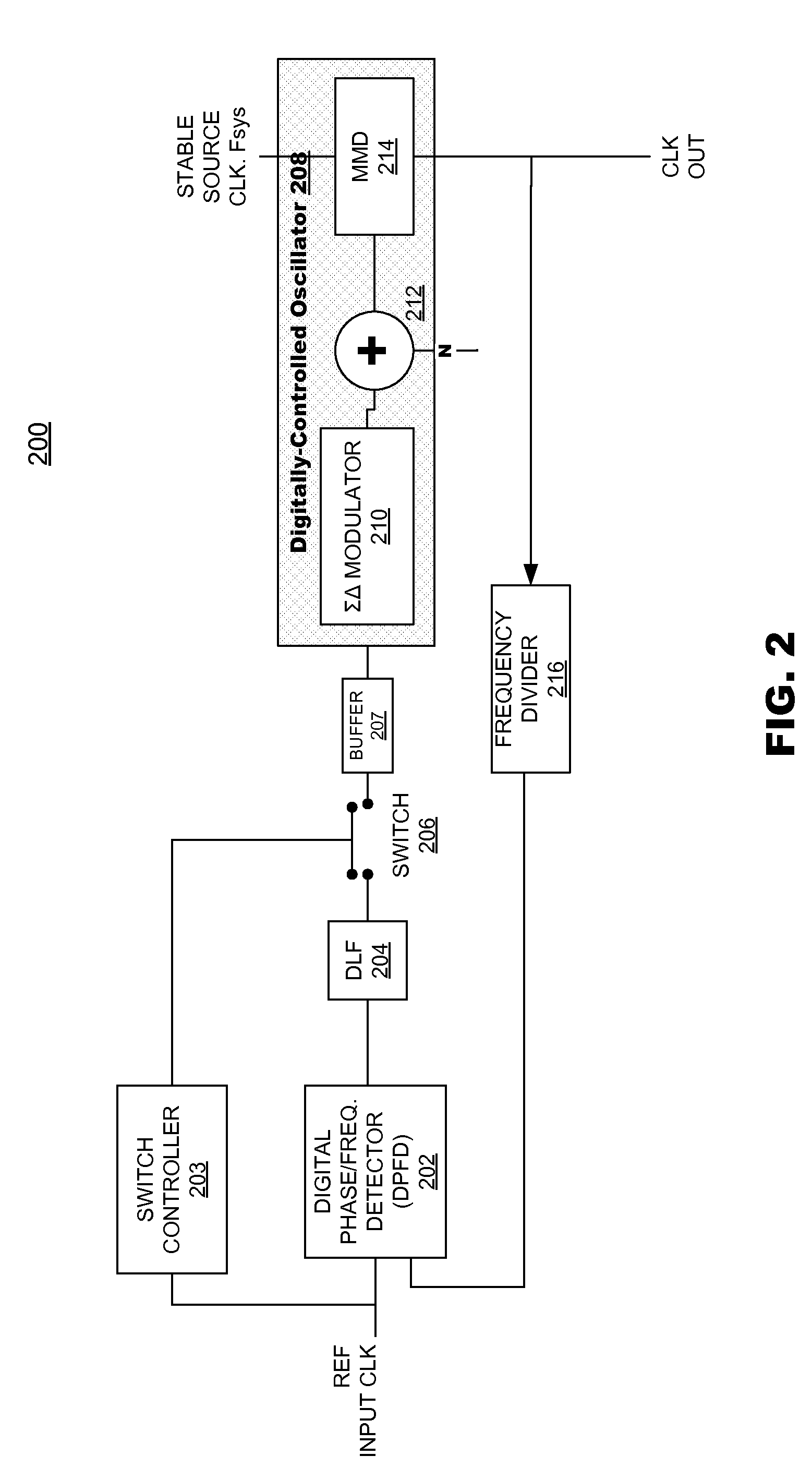
Embodiments of the present invention may provide clock system that may include a digital phase / frequency detector (DPFD), a buffer, a digitally-controlled oscillator (DCO) including a sigma-delta modulator (SDM), an adder, a first frequency divider. The DPFD may have a first input for a reference input clock and a second input for a feedback signal, and outputting a difference signal representing a phase and / or frequency difference between the reference input clock and the feedback signal. The buffer may be coupled to the DPFD for storing the difference signal over time. The sigma-delta modulator (SDM) may have a control input coupled to the buffer. The adder may have inputs coupled to the (SDM) and a source of an integer control word. The first frequency divider may have an input for a clock signal and a control input coupled to the adder, the DCO generating an output clock signal having an average frequency representing a frequency of the input clock signal divided by (N+F / M), in ...


PUM


Abstract

A clock system includes a digital phase/frequency detector (DPFD), a buffer, a digitally-controlled oscillator (DCO) including a sigma-delta modulator (SDM), an adder, a first frequency divider. The DPFD may have a first input for a reference input clock and a second input for a feedback signal, and outputting a difference signal representing a phase and/or frequency difference between the reference input clock and the feedback signal. The buffer may be coupled to the DPFD for accumulating the difference signal over time. The sigma-delta modulator (SDM) may have a control input coupled to the buffer. The adder may have inputs coupled to the (SDM) and a source of an integer control word. The first frequency divider may have an input for a clock signal and a control input coupled to the adder, the DCO generating an output clock signal having an average frequency representing a frequency of the input clock signal divided by (N+F/M), wherein N is determined by the integer control word and F/M is determined by an output of the SDM. The system clock also may include a phase-locked loop (PLL) including a phase/frequency detector that has a first input coupled to the output of the DCO and a second input that is phase-locked to the first input, and a second frequency divider coupled from the second input of the PLL to the second input of the DPFD.

Description

FIELD OF THE INVENTIONThe present invention is generally directed to a digital clock system that may be used to generate a clock for a circuit system. In particular, the present invention is directed to a clock system that may generate a highly stable and high performing clock using a digital phase-locked loop (DPLL) circuit and a fractional divider based digitally-controlled oscillator (DCO).BACKGROUND INFORMATIONDigital Phase Locked Loop (DPLL) circuits may be used to generate system clocks. The DPLL may generate a system clock based on a reference input clock. When the DPLL loses the reference input clock during operation, the DPLL operates in a holdover event. Certain systems may require their system clock to perform accurately even in the holdover events. The holdover frequency accuracy may be defined in terms of a maximum fractional frequency offset and drift over a period of time.Analog Devices Inc., the assignee of the present invention, manufactures integrated circuits that...

Claims


Application Information

Patent Timeline
IPC IPC(8): H03L7/08
CPCB60Q1/444H03L7/0992H03L7/0994H03L2207/50H03L7/18H03L7/23H03L7/235H03L7/146
Inventor NELSON, REUBEN PASCALZHU, DAN
Owner ANALOG DEVICES INC
Why Eureka
Try Eureka