Local oscillator with non-harmonic ratio between oscillator and RF frequencies using XOR operation with jitter estimation and correction

Active Publication Date: 2008-03-06
TEXAS INSTR INC
View PDF7 Cites 26 Cited by
  • Summary
  • Abstract
  • Description
  • Claims
  • Application Information

AI Technical Summary

Benefits of technology

[0025]Advantages of the LO generation schemes of the present invention include (1) ensuring that no frequency pulling effects occur since the LO frequency is equal to a non-integer multiple of the RF out

Problems solved by technology

A major problem associated with LO generation schemes such as that of FIG. 1 is their susceptibility to RF signal interference.
In particular, the resonator used in the circuit (especially inductor based resonators) often picks-up unwanted RF signals and the resonator frequency can be severely perturbed.
Causes of the pulling include undesired coupling to another frequency source (e.g., RF intermediate or output signals) or the influence of changes in the oscillator load impedance.
Transmission of a wideband signal in high frequency bands such as 5 GHz, however, requires complicated converters that run at very high frequencies.
Although the circuit generates fRF signals, a major disadvantage of using the polyphase filter is that they are typically large and inaccurate filters causing a potentially large IQ mismatch, i.e. LOI and LOQ are not strictly 90 degrees apart.
Two major disadvantages of this scheme, however, are (1) the fact that the second harmonic of the amplified RF signal at 2 fRF, can pull the oscillator away, since there could be a small offset between these two frequencies due to data modulation and (2) that the oscillator must be designed to twice the frequency (generally design at high frequencies tends to be more difficult).
The first disa

Method used


Image

  • Local oscillator with non-harmonic ratio between oscillator and RF frequencies using XOR operation with jitter estimation and correction
  • Local oscillator with non-harmonic ratio between oscillator and RF frequencies using XOR operation with jitter estimation and correction
  • Local oscillator with non-harmonic ratio between oscillator and RF frequencies using XOR operation with jitter estimation and correction

Examples


first embodiment

Non-Harmonic DCO With XOR and BPF (Offset LO Generator)

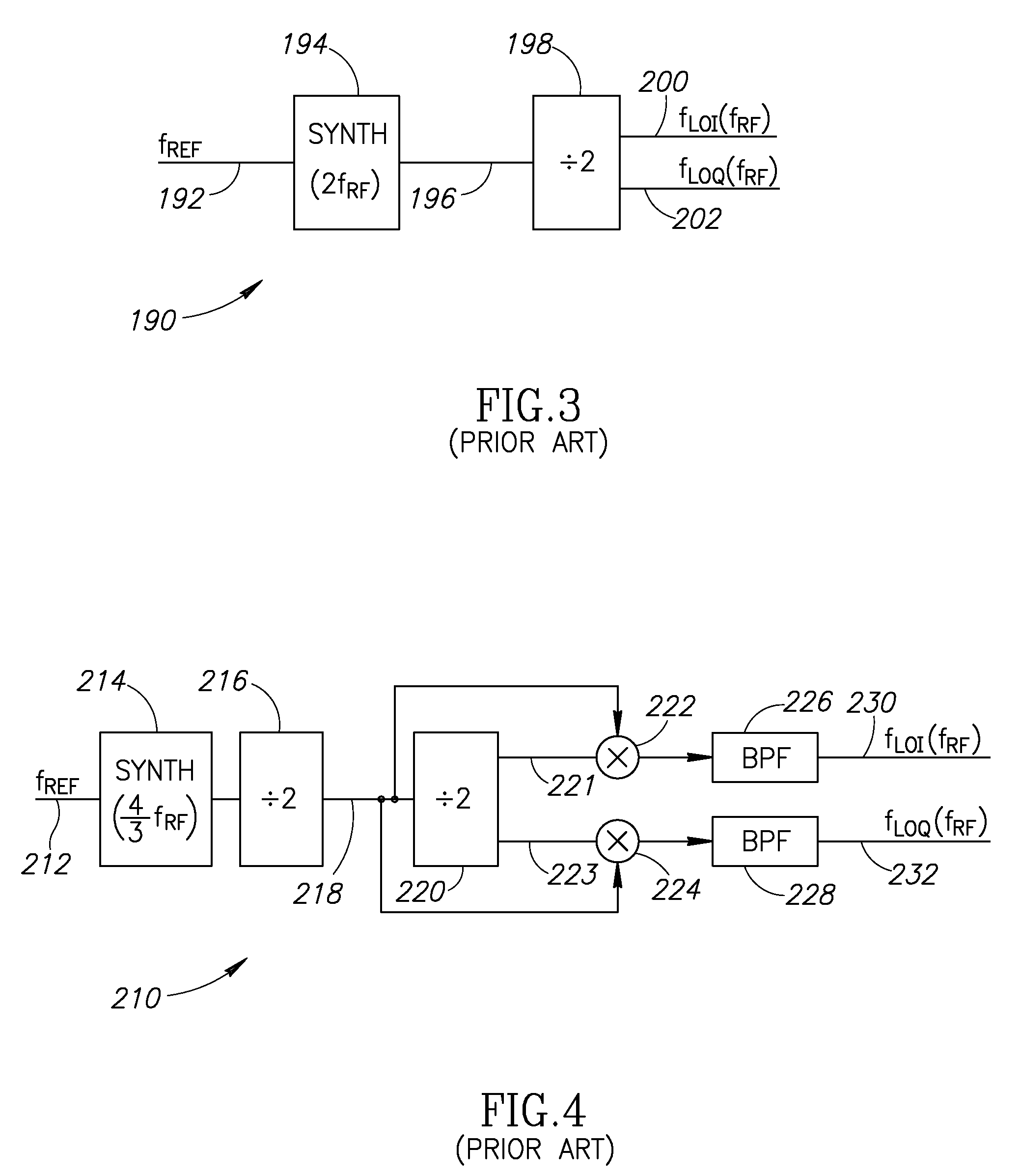
[0097]In a first LO generation scheme, the basic PLL structure runs at 4 / 3 the desired frequency fRF. This frequency is divided by two to obtain in-phase and quadrature square waves at 2 / 3 fRF. It is noted that the division by two would not be necessary if the quadrature generation of the square wave clocks is achieved through some other means. In this case, the oscillator could operate at a lower frequency. The in-phase signal is divided by two again to obtain in-phase and quadrature square waves at 1 / 3 fRF. The signals are then logically mixed using XOR operations to obtain I and Q branch signals containing spectral spurs every ((2n+1) / 3)fRF, where n is an integer. Since the spurs are located in non-disturbing bands, they can be filtered out. In a deep-submicron chip, for example, there is a need for a digital implementation of the above described LO generation scheme.

[0098]A block diagram illustrating a first embodiment of th...

second embodiment

Non-Harmonic DCO With XOR and Jitter Compensation #1

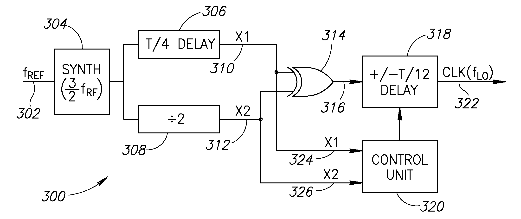
[0111]A block diagram illustrating a second embodiment of the local oscillator generation mechanism of the present invention is shown in FIG. 11. The circuit, generally referenced 300, comprises a synthesizer 304, T / 4 delay 306, frequency divider 308, XOR gate 314, ±T / 12 delay 318 and control unit 320.

[0112]In operation, a reference signal fREF 302 is input to a synthesizer tuned to exactly 2 / 3 fRF. Alternatively, the 4 / 3 fRF configuration with a quadrature divider generating 90-degree spaced clocks could be used. In this case, the T / 4 delay would not be needed. The digital output of the synthesizer is input to a T / 4 delay 306 and a divide by two circuit 308. The outputs of both blocks are XORed together via XOR circuit 314. The output of the XOR circuit is input to a programmable ±T / 12 delay 318. Since the absolute delay of block 318 does not change the overall structure, a “negative delay” can be achieved using two paths whose re...

third embodiment

Non-Harmonic DCO With XOR and Jitter Compensation #2

[0116]A block diagram illustrating a third embodiment of the local oscillator generation mechanism of the present invention is shown in FIG. 13. The circuit, generally referenced 340, is a second implementation of the local oscillator generation scheme of FIG. 11. The circuit 340 comprises a synthesizer 344, T / 4 delay 348, frequency divider 350, −T / 12 delay circuit 353, T / 12 delay circuit 354, multiplexer 358 and control unit (CU) 360.

[0117]In operation, a reference signal 342 is input to a synthesizer 344 tuned to exactly 2 / 3 fRF. The digital signal 346 output of the synthesizer is input to both a T / 4 delay circuit 348 as well as divide by two circuit 350, which are operative to generate signals X1362 and X2364, respectively. Note that here too, as described before, the T / 4 delay circuit 348 is not needed if a quadrature generation of the 346 signal is available. Signal X1 undergoes delays of −T / 12 via delay circuit 352 and +T / 12 ...


PUM


Abstract

A novel and useful apparatus for and method of local oscillator (LO) generation with non-integer multiplication ratio between the local oscillator and RF frequencies. The LO generation schemes presented are operative to generate I and Q square waves at a designated frequency while avoiding the well known issue of harmonic pulling. The use of analog mixers of the prior art is avoided and replaced with an XOR gate configured to generate the correct average frequency. The edges are dynamically adjusted by ±T/12 or zero based on the state of the controlled oscillator down-divided clock.

Description

REFERENCE TO PRIORITY APPLICATION[0001]This application claims priority to U.S. Provisional Application Ser. No. 60 / 823,837, filed Aug. 29, 2006, entitled “Generation of Local-Oscillator Signal with Non-Integer Multiplication Ratio Between the Local-Oscillator and the RF Frequencies”, incorporated herein by reference in its entirety.FIELD OF THE INVENTION[0002]The present invention relates to the field of data communications and more particularly relates to a local oscillator (LO) circuit with non-integer multiplication ratio between the local oscillator and RF frequencies.BACKGROUND OF THE INVENTION[0003]The use of local oscillator generation circuits for wireless transceivers is well known in the art. The local oscillator is generated as a continuous wave (CW) and is then used for quadrature modulation or demodulation of transmitted and received signals respectively. Alternatively, the oscillator can also perform frequency modulation as part of a polar transmitter architecture sys...

Claims


Application Information

Patent Timeline
IPC IPC(8): H03B21/01H03B21/00
CPCH03B21/00
Inventor STASZEWSKI, ROBERT B.TAL, NIR
Owner TEXAS INSTR INC
Why Eureka
Try Eureka