
Touch panel and electronic device using the same

a technology of electronic devices and touch panels, applied in the field of touch panels and electronic devices, can solve problems such as short product li

Inactive Publication Date: 2011-02-10
HONG FU JIN PRECISION IND (SHENZHEN) CO LTD +1
View PDF6 Cites 5 Cited by
  • Summary
  • Abstract
  • Description
  • Claims
  • Application Information

AI Technical Summary

Benefits of technology

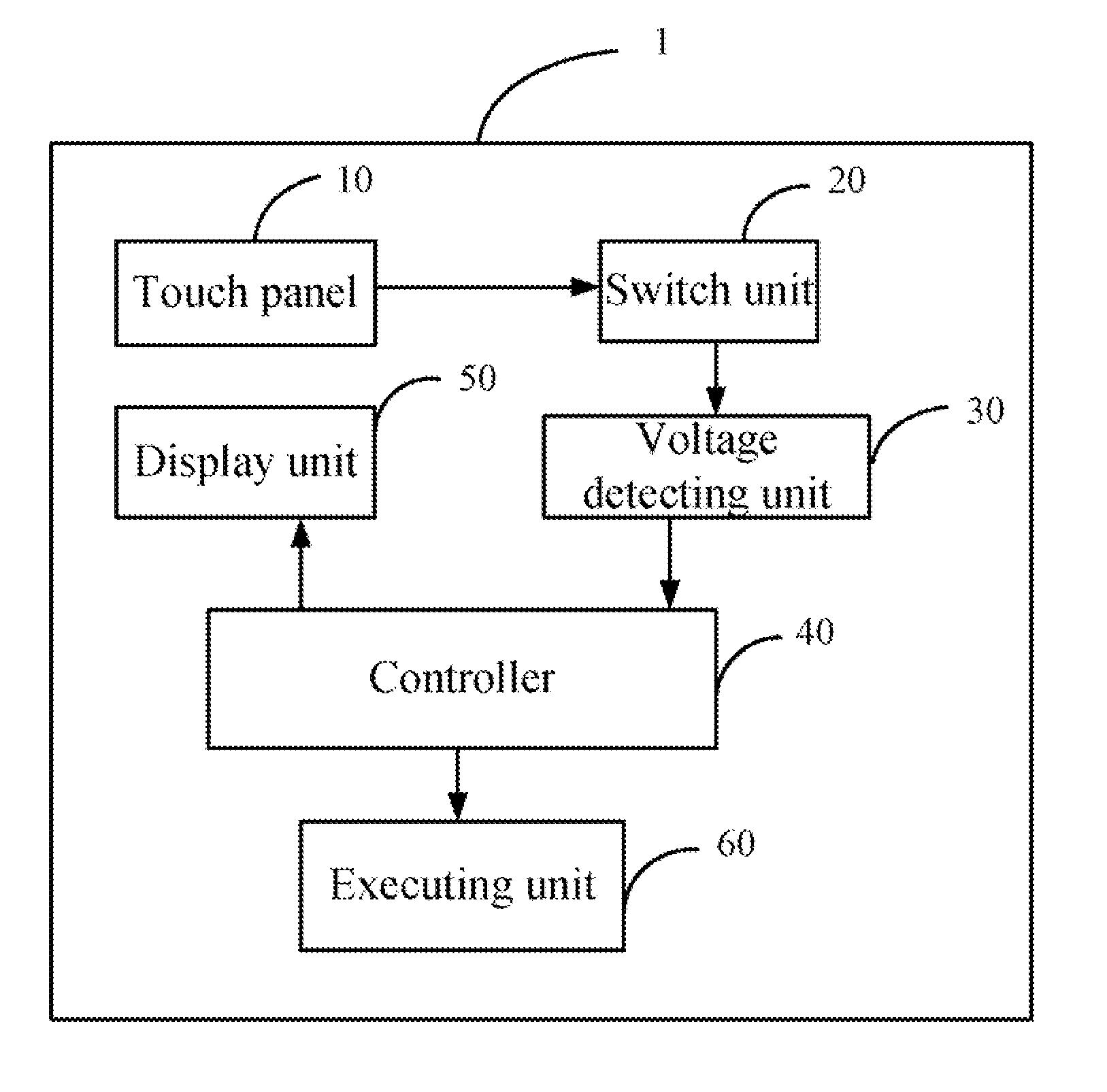
The present patent relates to a touch panel and an electronic device using the touch panel. The technical effects of the patent include providing a flexible touch panel that can detect touch accurately and easily, and improving the lifespan of the flexible electrode plate. The touch panel includes a flexible electrode layer and a microcapsule layer that are electrically connected to each other, allowing for the detection of touch through the distribution of charged particles in the microcapsules. The electronic device using the touch panel includes a switch unit for controlling the electrical connection between the electrode units and a voltage detecting unit.

Problems solved by technology

As described above, the flexible electrode plate must be deformed with each, resulting in a short product lifespan.

Method used


Image

  • Touch panel and electronic device using the same
  • Touch panel and electronic device using the same
  • Touch panel and electronic device using the same

Examples


Embodiment Construction

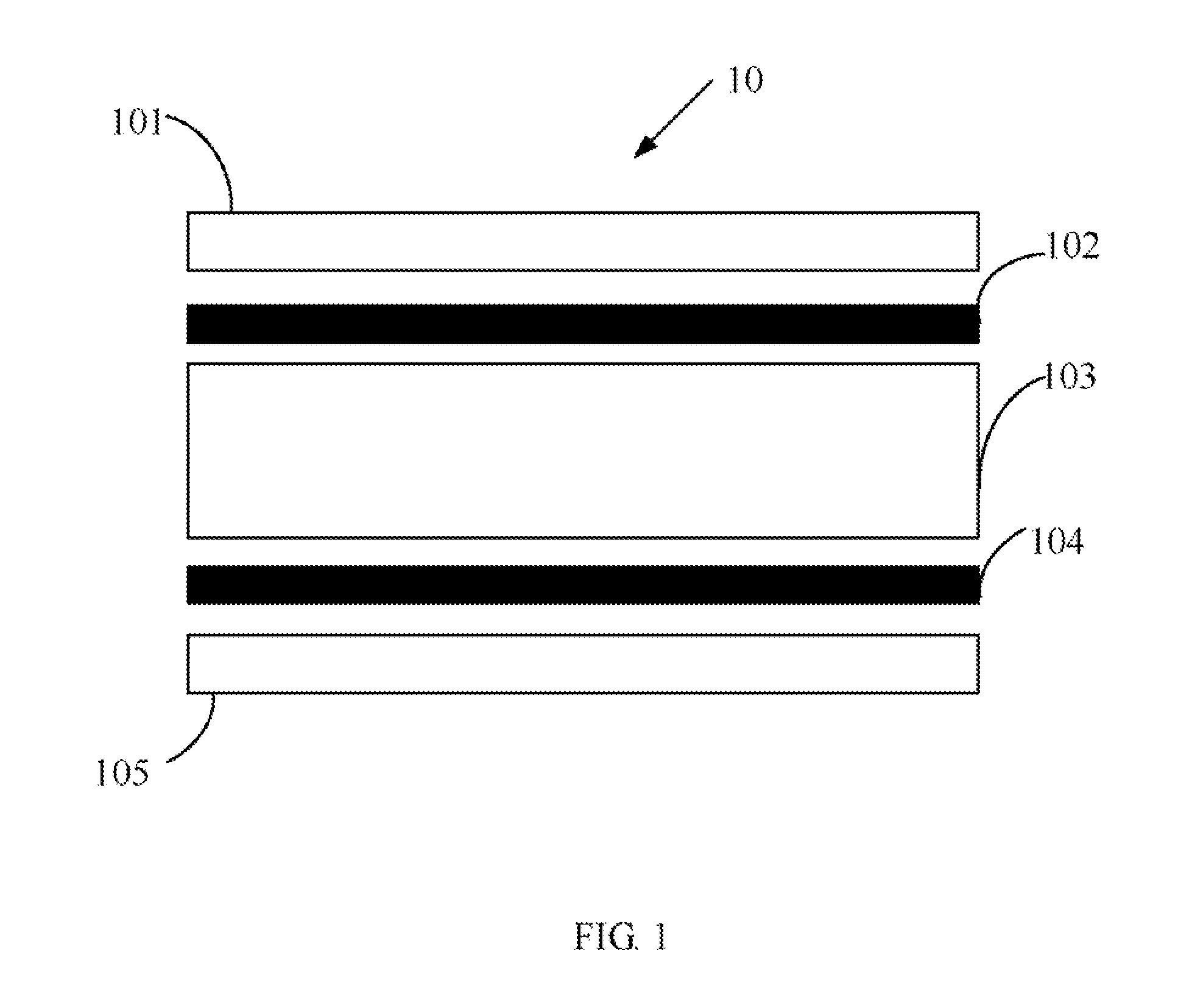
[0012]Referring to FIG. 1, an embodiment of a touch panel 10 is illustrated. The touch panel 10 includes a touch layer 101, a first Indium Tin Oxide (ITO) electrode layer 102, a microcapsule layer 103, a second ITO layer 104, and a substrate 105. The touch layer 101 is exposed to users. In the embodiment, the touch layer 101 is made of conductive material. The first ITO layer 102 is disposed below the touch layer 101. The microcapsule layer 103 is disposed between the first ITO layer 102 and the second ITO layer 104. The microcapsule layer 103 is electrically connected to the first ITO layer 102 and the second ITO layer 104. The substrate 105 is configured for supporting the touch layer 101, the first ITO layer 102, the microcapsule layer 103, and the second ITO layer 104.

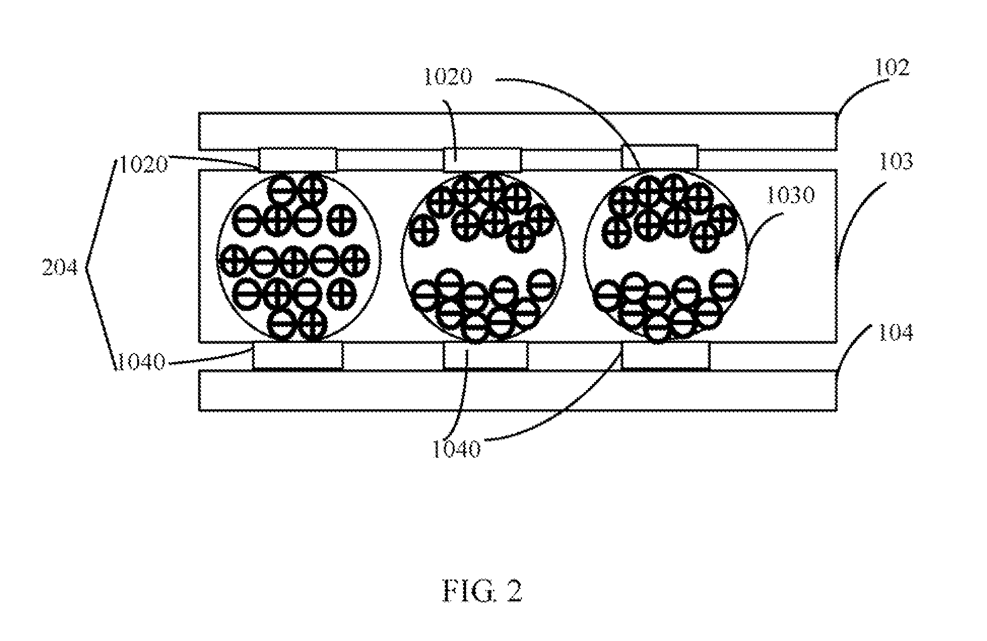
[0013]Referring also to FIG. 2, the first ITO layer 102 includes a plurality of first ITO electrodes 1020, and the second ITO layer 104 includes a plurality of second ITO electrodes 1040. Each of the first ITO elec...


PUM


Abstract

A touch panel includes a touch layer, a first Indium Tin Oxide (ITO) electrode layer, a second ITO layer, and a microcapsule layer. The first ITO electrode layer includes a plurality of first ITO electrode. The second ITO electrode layer includes a plurality of second ITO electrodes. Each of the first ITO electrodes and one corresponding second ITO electrode forms an electrode unit. The microcapsule layer includes a plurality of microcapsules. Each microcapsule is connected to the first ITO electrode and the corresponding second ITO electrode. Each microcapsule comprises a plurality of positively charged particles and negatively charged particles. When the touch panel is touched, the distribution of the positively and negatively charged particles in the microcapsule corresponding to the touch portion of the touch layer is placed in a polarization state. An electronic device using the touch panel is also provided.

Description

BACKGROUND[0001]1. Technical Field[0002]The present disclosure relates to touch panels and electronic devices and, particularly, to an electronic device using a touch panel.[0003]2. Description of Related Art[0004]Generally, there are three types of touch panels, the resistance film type, the surface ultrasonic wave type, and the electrostatic capacity type. The resistance film type touch panel is very popularly used.[0005]The resistance film type touch panel has a structure in which a flexible transparent electrode plate is provided with a transparent electrode layer, and a fixed (rigid) transparent electrode plate is also provided with a transparent electrode layer. The flexible transparent electrode plate and the rigid transparent electrode plate are arranged spaced apart from each other via a spacer such that their transparent electrode layers face each other. When the touch panel is pressed, the flexible electrode plate is deformed, and a corresponding point of the transparent ...

Claims


Application Information

Patent Timeline
Patent Type & Authority Applications(United States)
IPC IPC(8): G06F3/041
CPCG06F3/047G06F3/046
Inventor YANG, SONG-LING
Owner HONG FU JIN PRECISION IND (SHENZHEN) CO LTD
Learn More