Orthogonally separable light bar

Inactive Publication Date: 2011-02-10
ILLUMITEX INC
View PDF18 Cites 8 Cited by
  • Summary
  • Abstract
  • Description
  • Claims
  • Application Information

AI Technical Summary

Benefits of technology

[0011]Embodiments of optical systems described herein provide advantages over traditional systems of using phosphors in conjunction with light sources by reducing heating at the light source due to absorption of down-converted light.
[0012]Embodiments described herein provide another advantage by potentially leading to lower thermal rise due to Stoke's shift.
[0013]Embodiments described herein provide yet another advantage because a light source's temperature no longer has a significant influence on the phosphor temperature and vice versa.
[0014]Embodiments described herein provide yet ano

Problems solved by technology

This implies that per unit area, the flux density of pump energy on the phosp

Method used


Image

  • Orthogonally separable light bar
  • Orthogonally separable light bar
  • Orthogonally separable light bar

Examples


Embodiment Construction

[0033]The disclosure and various features and advantageous details thereof are explained more fully with reference to the exemplary, and therefore non-limiting, embodiments illustrated in the accompanying drawings and detailed in the following description. Descriptions of known starting materials and processes may be omitted so as not to unnecessarily obscure the disclosure in detail. It should be understood, however, that the detailed description and the specific examples, while indicating the preferred embodiments, are given by way of illustration only and not by way of limitation. Various substitutions, modifications, additions and / or rearrangements within the spirit and / or scope of the underlying inventive concept will become apparent to those skilled in the art from this disclosure.

[0034]As used herein, the terms “comprises,”“comprising,”“includes,”“including,”“has,”“having” or any other variation thereof, are intended to cover a non-exclusive inclusion. For example, a process,...


PUM


Abstract

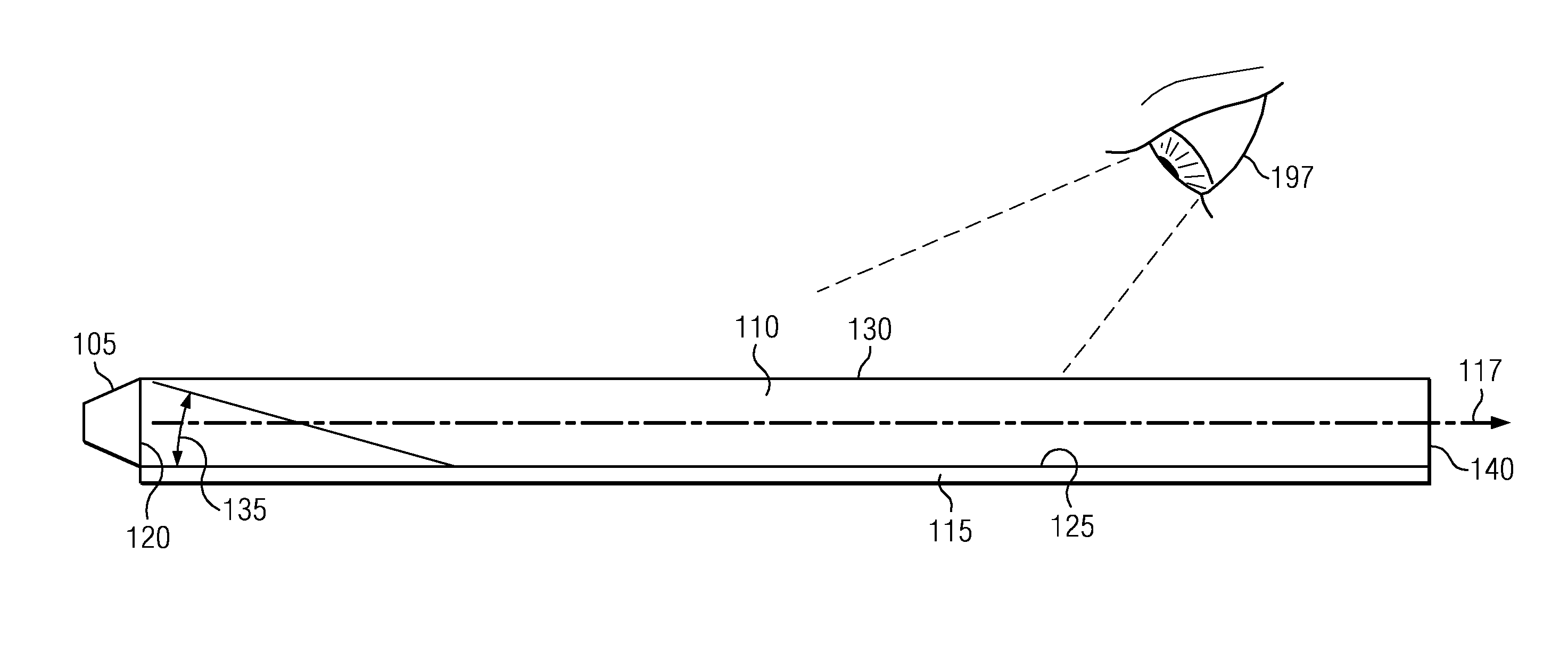
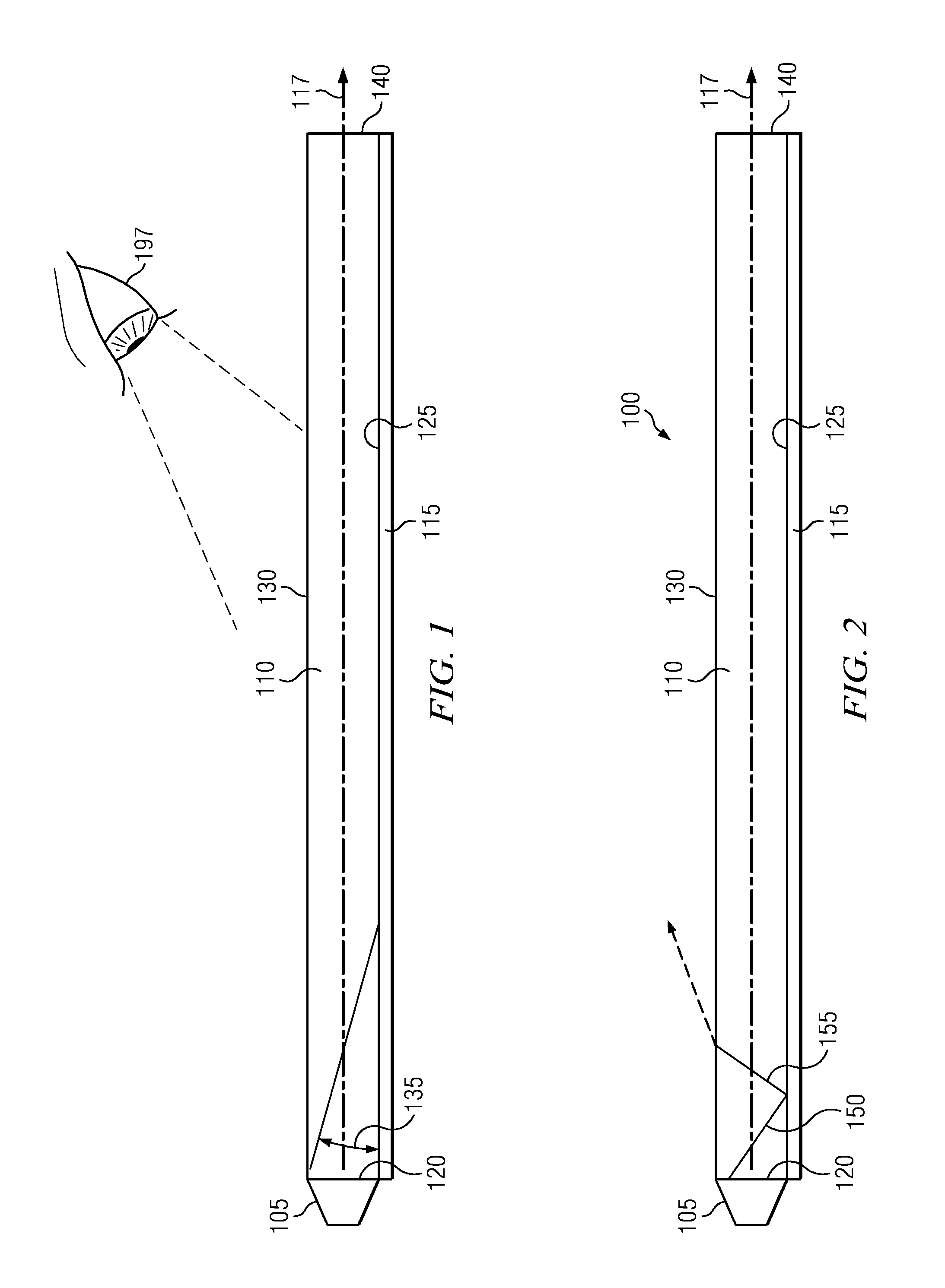
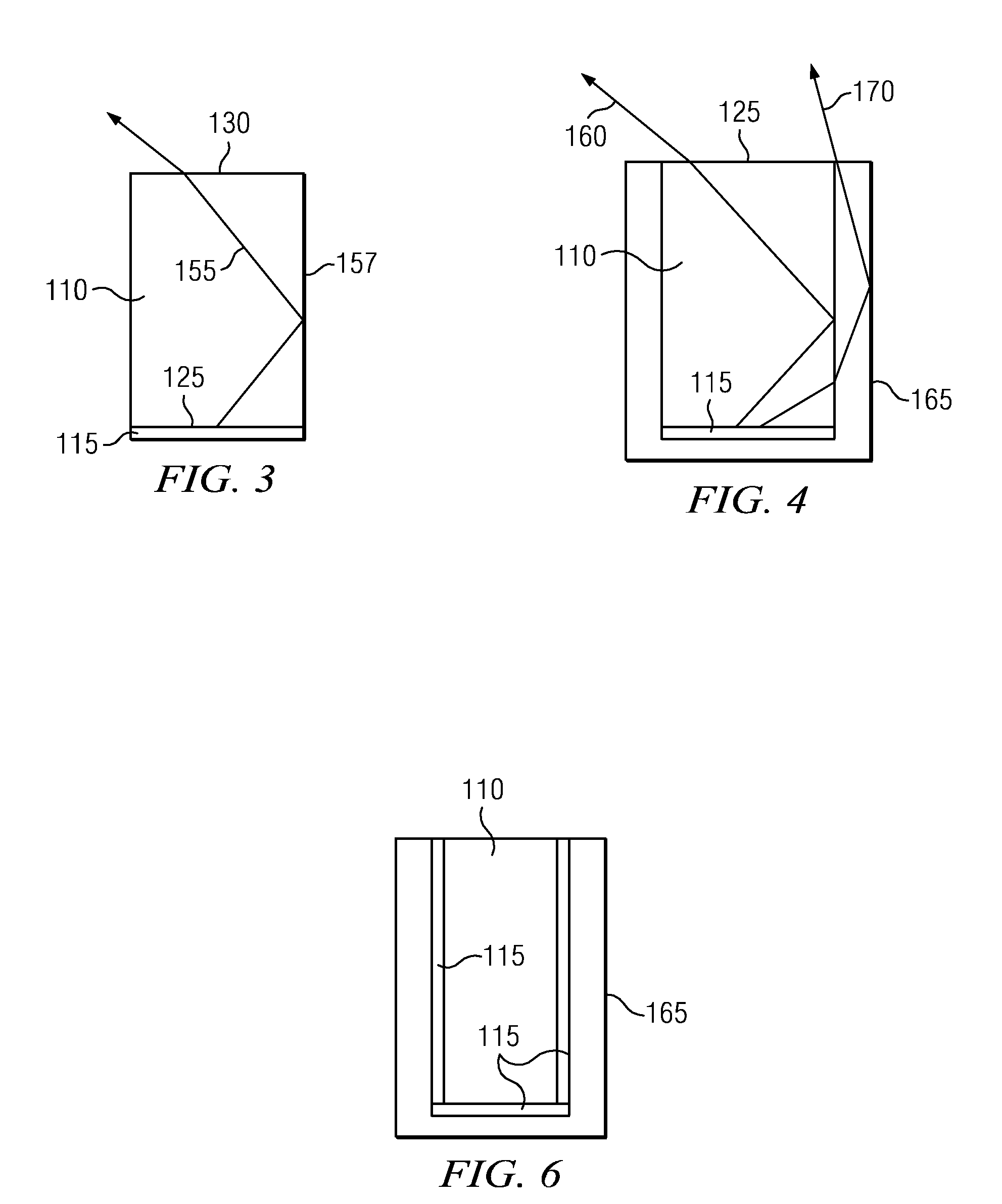
Embodiments described herein provide optical systems in which phosphors are used to down-convert light. In general, optical systems can include a light guide configured to propagate light from an entrance face to a distal end along a propagation axis using total internal reflection. A phosphor layer can be disposed orthogonal to the entrance surface of the light guide.

Description

RELATED APPLICATION[0001]This application claims the benefit of priority under 35 USC §119(e) to U.S. Provisional Patent Application Ser. No. 61 / 229,642 by inventors Dung T. Duong and Hyunchul Ko, entitled “Orthogonally Separable Light Bar”, filed Jul. 29, 2009, the entire contents of which are hereby expressly incorporated by reference for all purposes.TECHNICAL FIELD[0002]Embodiments described herein relate to optical systems. More particularly, embodiments described herein relate to optical systems using phosphors to down convert light.BACKGROUND[0003]LEDs are used to generate light for a variety of applications. In some cases, phosphors are used in conjunction with the LEDs to produce a desired color of light. In traditional systems of using phosphors with LEDs, phosphors are coated on a dome that surrounds the LED. These systems, however, suffer from heat related inefficiencies.[0004]An LED inherently heats when transforming electrical energy to light. The addition of phosphors...

Claims


Application Information

Patent Timeline
IPC IPC(8): F21V7/22F21V9/40
CPCF21V7/04G02B6/005F21Y2101/02F21K9/64F21Y2115/10
Inventor DUONG, DUNG T.KO, HYUNCHUL
Owner ILLUMITEX INC
Why Eureka
Try Eureka