Laboratory scale continuous flow hydrogenation process

a hydrogenation process and laboratory technology, applied in the direction of fluid pressure control, gas-gas reaction process, physical/chemical process catalysts, etc., can solve the problems of increasing the dimensions and operational risks of the apparatus, the relative speed and automation of synthesis/derivatisation, and the use of structural elements in the hydrogenation performed under supercritical conditions. , to achieve the effect of fast and automated

Active Publication Date: 2011-02-10
THALESNANO ZRT
View PDF7 Cites 1 Cited by
  • Summary
  • Abstract
  • Description
  • Claims
  • Application Information

AI Technical Summary

Benefits of technology

[0015]Accordingly, the object of the invention is to develop such a laboratory scale continuous flow hydrogenation process by means of which on the one hand one or more of the above disadvantages can be eliminated or significantly reduced, that is, in particular, hydrogenation reactions can be accomplished under normal, i.e. not supercritical conditions and without the formation of undesired byproducts as a result of in-situ hydrogen production, on the other hand even a library amount of molecules can be derived in a fast and automated manner.
[0016]As a result of the experiments carried out in order to find a solution for achieving one or more of the above objects, it was concluded that by providing the sample to be hydrogenated separately from the solvent used to dissolve it, and by creating and maintaining a continuous flow of a base solution through the laboratory scale hydrogenation apparatus at a constant volume rate, it becomes possible to adjust the pressure within the apparatus in such a manner that the highest pressure values building up at the place of the hydrogenation reaction do not exceed pressure values related to supercritical conditions, which means that the hydrogenation process can be conducted under normal conditions.

Problems solved by technology

This problem especially strongly arises in the field of combinatorial chemical syntheses, where a relatively fast and automated synthesis / derivatisation, as well as analysis of molecules of a whole library is needed.
A common disadvantage of the above discussed apparatuses and processes operating essentially under supercritical conditions is that hydrogenation performed under supercritical conditions requires the usage of structural elements handling the fluid (eg. feeding thereof, inducing a change in its pressure and temperature and accomplishing its separation).
The application of these structural elements increases the dimensions and the operational risk of the apparatuses, makes the construction and the operation of the apparatuses, as well as the effectuation of the hydrogenating processes more complicated and significantly raises the production costs.
A further disadvantage of said apparatuses and processes is that depending on the starting materials used for the in-situ production, i.e. within the reactor, of hydrogen needed to perform the hydrogenation, besides the final product, undesired and reactive by-product(s) also build(s) up in certain cases.
Furthermore, the application of the apparatuses concerned is also disadvantageous when the final derivatisation operations of combinatorial chemistry are performed, as in this case the library synthesis is required to take place as rapidly as possible with the least possible extent of human interference.

Method used


Image

  • Laboratory scale continuous flow hydrogenation process
  • Laboratory scale continuous flow hydrogenation process
  • Laboratory scale continuous flow hydrogenation process

Examples


Embodiment Construction

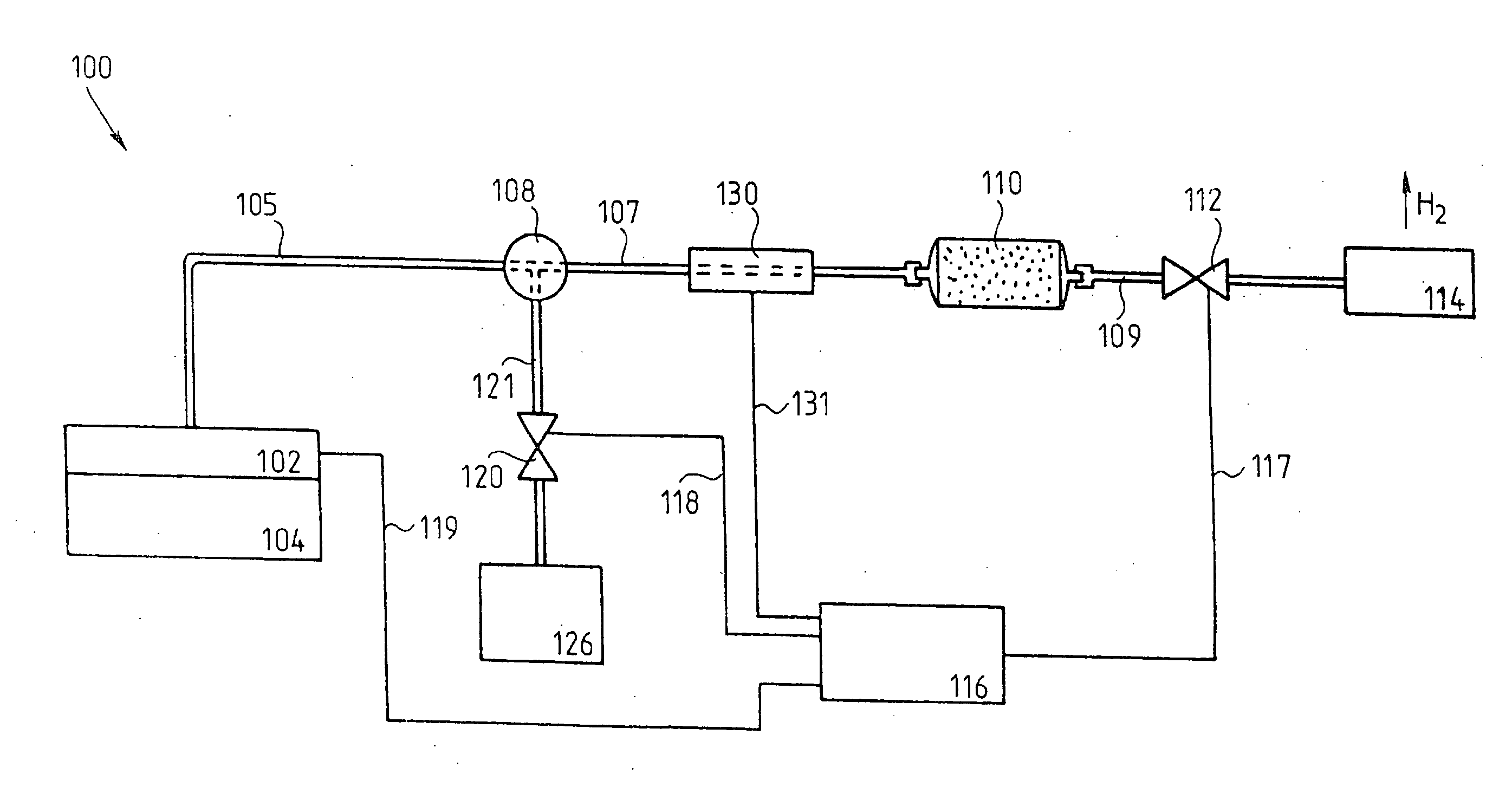
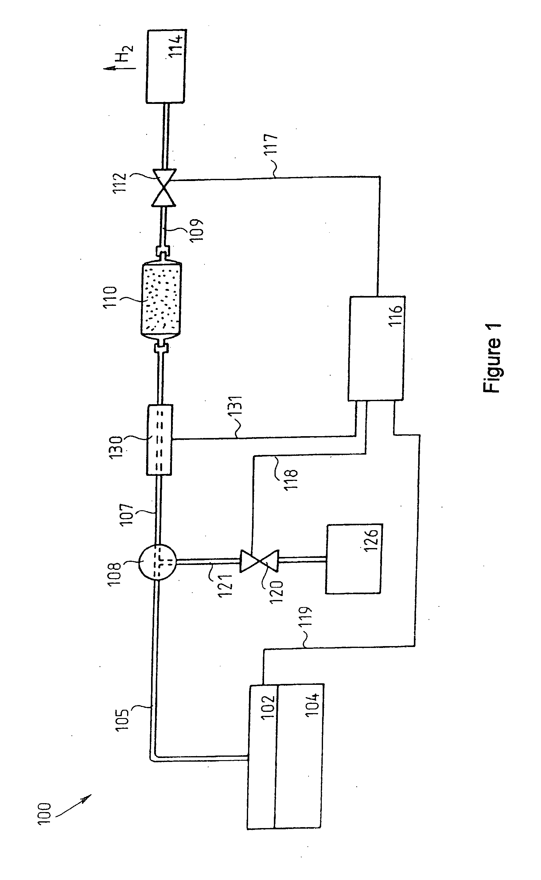
[0026]The hydrogenation apparatus 100 shown schematically in FIG. 1 comprises a reservoir 104 equipped with a feed pump 102, a collecting element 108, a hydrogenation reactor 110, a pressure-adjusting unit 112, a product receptacle 114, a controlling electronics 116, a valve 120 and a hydrogen source 126. The inlet of the feed pump 102 is in fluid communication with the reservoir 104, while its outlet is connected through a pipe 105 to a first inlet of the collecting element 108. The hydrogen source 126 is connected to a second inlet of the collecting element 108 through a pipe 121 and the valve 120 inserted into the pipe 121. The outlet of the collecting element 108 is connected through a pipe 107 to the inlet of the hydrogenation reactor 110. The outlet of the hydrogenation reactor 110 opens into the product receptacle 114 through a pipe 109 and the pressure-adjusting unit 112 inserted into the pipe 109. As a result of connecting the listed elements to each other, the hydrogenatio...


PUM

PropertyMeasurementUnit
pressureaaaaaaaaaa
partial pressureaaaaaaaaaa

Abstract

A process for hydrogenating a sample in a pressure range below supercritical pressure values includes supplying at least a solvent of the sample to be hydrogenated by a feed pump with a constant volume rate into a flow path to create a base solution; adding the sample being dissolved into the flow path; feeding hydrogen into the flow path through a valve configured to transmit hydrogen only into a single direction; leading the dissolved sample in the presence of a catalyst through a hydrogenation reactor, where the reactor is inserted into a section of the flow path located after the hydrogen feeding position; maintaining the pressure of the reaction in a given pressure range by element of a pressure-adjusting unit, and collecting a hydrogenate formed within the hydrogenation reactor in a product receptacle connected to the end of the flow path.

Description

CROSS REFERENCE TO RELATED APPLICATIONS[0001]This application is a divisional of co-pending application Ser. No. 11 / 593,601 filed on Nov. 7, 2006, which is a Continuation in part of International Application No. PCT / HU05 / 00046 filed on May 9, 2005, which claims priority to Hungarian Applications No. P 04 01727 filed on Aug. 23, 2004 and No. P 04 00944 filed on May 7, 2004. The entire contents of each of the above-identified applications are hereby incorporated by reference.BACKGROUND OF THE INVENTION[0002]1. Field of the Invention[0003]The invention relates to a laboratory scale continuous flow hydrogenation process of given samples under normal, i.e. not supercritical conditions. In particular, the invention relates to a laboratory scale continuous flow hydrogenation process exploiting a laboratory scale continuous flow hydrogenation apparatus comprising a reservoir, a feed pump, a collecting element with two inlets and an outlet, a hydrogenation reactor and a pressure-adjusting un...

Claims


Application Information

Patent Timeline
Patent Type & Authority Applications(United States)
IPC IPC(8): C07D209/04C07C209/36B01J10/00B01J23/44B01L5/00
CPCB01J10/002B01J10/007B01J23/44B01J2208/00539B01L5/00B01J2219/00011B01J2219/0002B01J2219/00038B01J2208/00548
Inventor DARVAS, FERENCGODORHAZY, LAJOSKARANCSI, TAMASSZALAY, DANIELBONCZ, FERENCURGE, LASZLO
Owner THALESNANO ZRT
Why Eureka
Try Eureka