Reflex sight for weapon

a technology for reflex sights and weapons, applied in the field of reflex sights for weapons, can solve the problem that the optical power of the see-through scene is normally non-adjustabl

Inactive Publication Date: 2011-02-17
SIROCCO VISION
View PDF5 Cites 15 Cited by
  • Summary
  • Abstract
  • Description
  • Claims
  • Application Information

AI Technical Summary

Benefits of technology

[0005]The present invention seeks to provide a reflex sight with a dy

Problems solved by technology

The optical power of the see-throug

Method used


Image

  • Reflex sight for weapon
  • Reflex sight for weapon
  • Reflex sight for weapon

Examples


Embodiment Construction

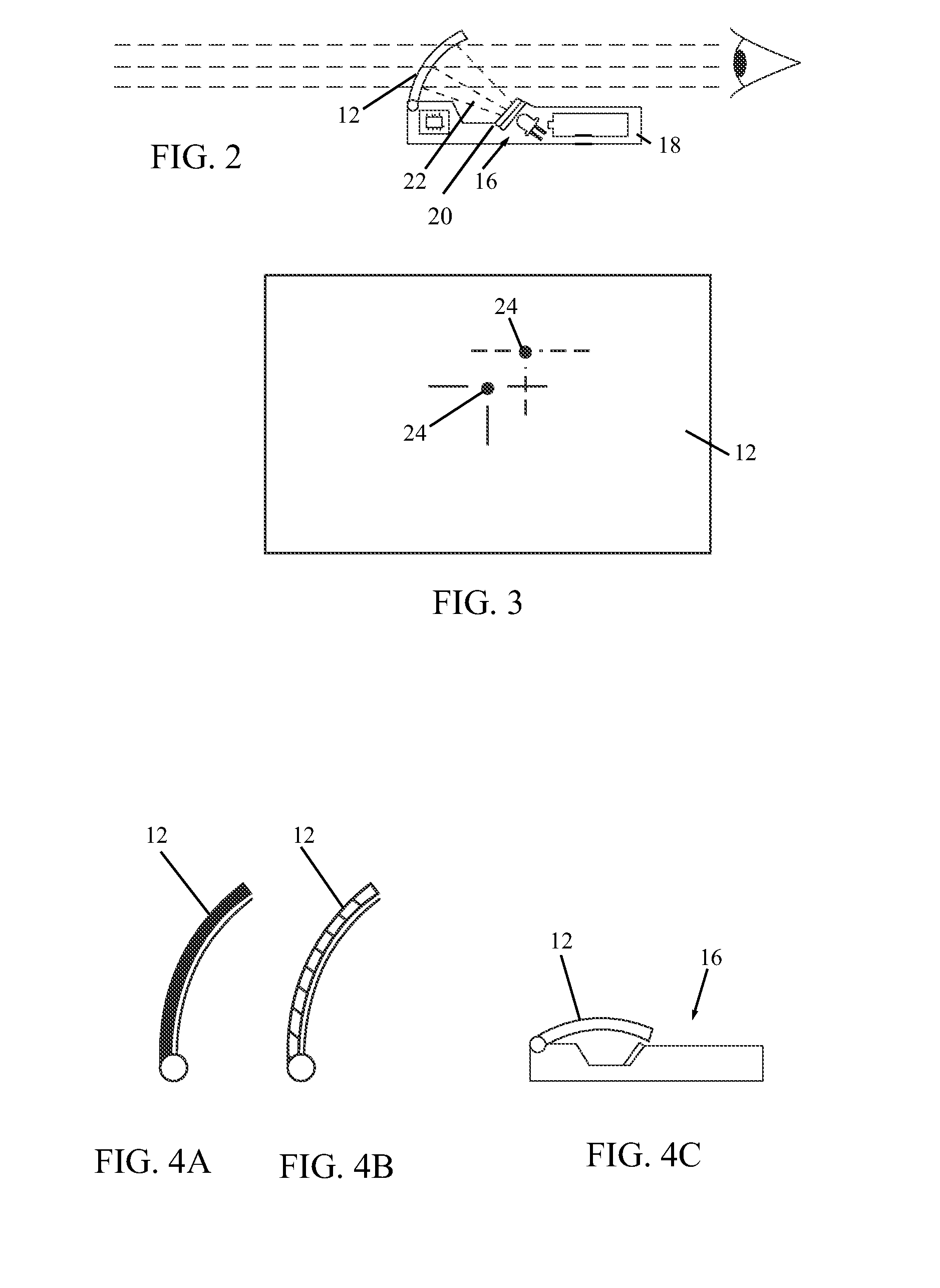
[0020]Reference is now made to FIGS. 1-7, which illustrate various features of a weapons reflex sight 10, in accordance with an embodiment of the present invention.

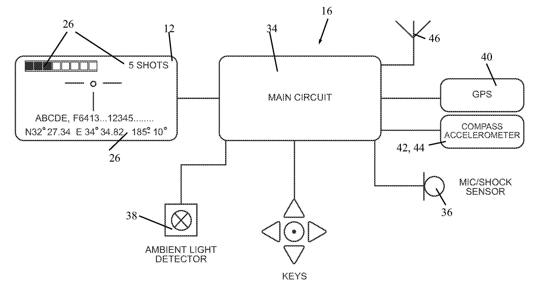
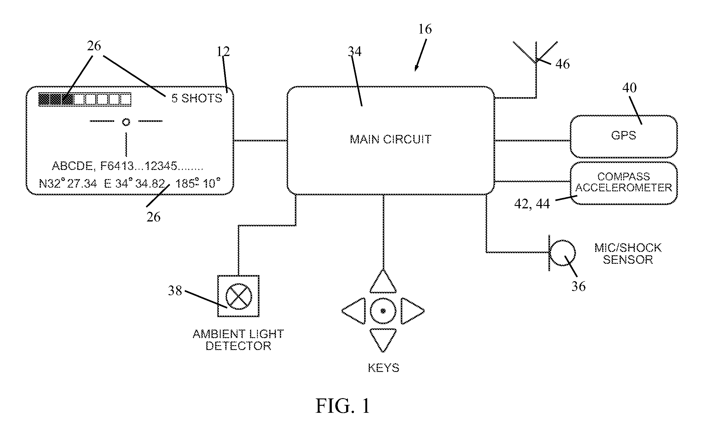
[0021]Reflex sight 10, which is mountable on a weapon 14, includes a display substrate 12 mounted on an optics module 16, which is disposed in a housing 18. Optics module 16 may include a computer-generated imagery (CGI) system 20 and suitable optical elements (lenses, mirrors, filters, LCD, OLED, LED etc.) for generating images and projecting a beam 22 of the images on display substrate (also called display screen) 12. It is noted that optics module 16 may include the display screen 12; the module has the optical power capacity to generate the virtual image. As is explained further below, the images include an aimpoint 24 for aiming at a target and information 26 related to use of the weapon 14. As seen in FIG. 3, the position of the aimpoint 24 may be adjusted, such as by commands from the optics module 16.

[0022]Housing...


PUM


Abstract

A weapons reflex sight including a display substrate mounted on a weapon, and an optics module, disposed in a housing, the optics module including a computer-generated imagery (CGI) system and optical elements for generating images and projecting a beam of the images on the display substrate, the images including an aimpoint for aiming at a target and information related to use of the weapon.

Description

FIELD OF THE INVENTION[0001]The present invention relates generally to reflex sights for weapons (e.g., rifles or handguns), and particularly to a reflex sight with a dynamic information display.BACKGROUND OF THE INVENTION[0002]Reflex sights for weapons are well known in the art. Such sights use an image of a reticle reflected from a semi-transparent mirror surface, through which mirror the shooter views the target. Optics cause the reticle image to appear at or near infinity, parallax free, and in focus with the target. The optics may be a refracting lens in the system that collimates the reticle image. The mirror surface may be concave so that it collimates the reticle image as it reflects it. The sight magnification is 1× unity.[0003]“Heads-Up Display” (HUD) reflex sights are known for use on weapons. The HUD or reflex sight is made up of an optical collimating reflector, mechanical adjustments and packaging, and an electronic light source. Conventional optical methods for collim...

Claims


Application Information

Patent Timeline
IPC IPC(8): F41G1/30F41A9/62G01C21/00
CPCF41G1/345
Inventor RAVIV, RONIGANOR, LIRANLIMONCHIK, GIL
Owner SIROCCO VISION
Why Eureka
Try Eureka