
Roof mounting support for photovoltaic modules on uneven roofs

a technology for photovoltaic modules and roofs, applied in photovoltaics, heat collector mounting/support, sustainable buildings, etc., can solve problems such as sealing damage to roof panels

Inactive Publication Date: 2011-02-17
ADENSIS
View PDF10 Cites 44 Cited by
  • Summary
  • Abstract
  • Description
  • Claims
  • Application Information

AI Technical Summary

Benefits of technology

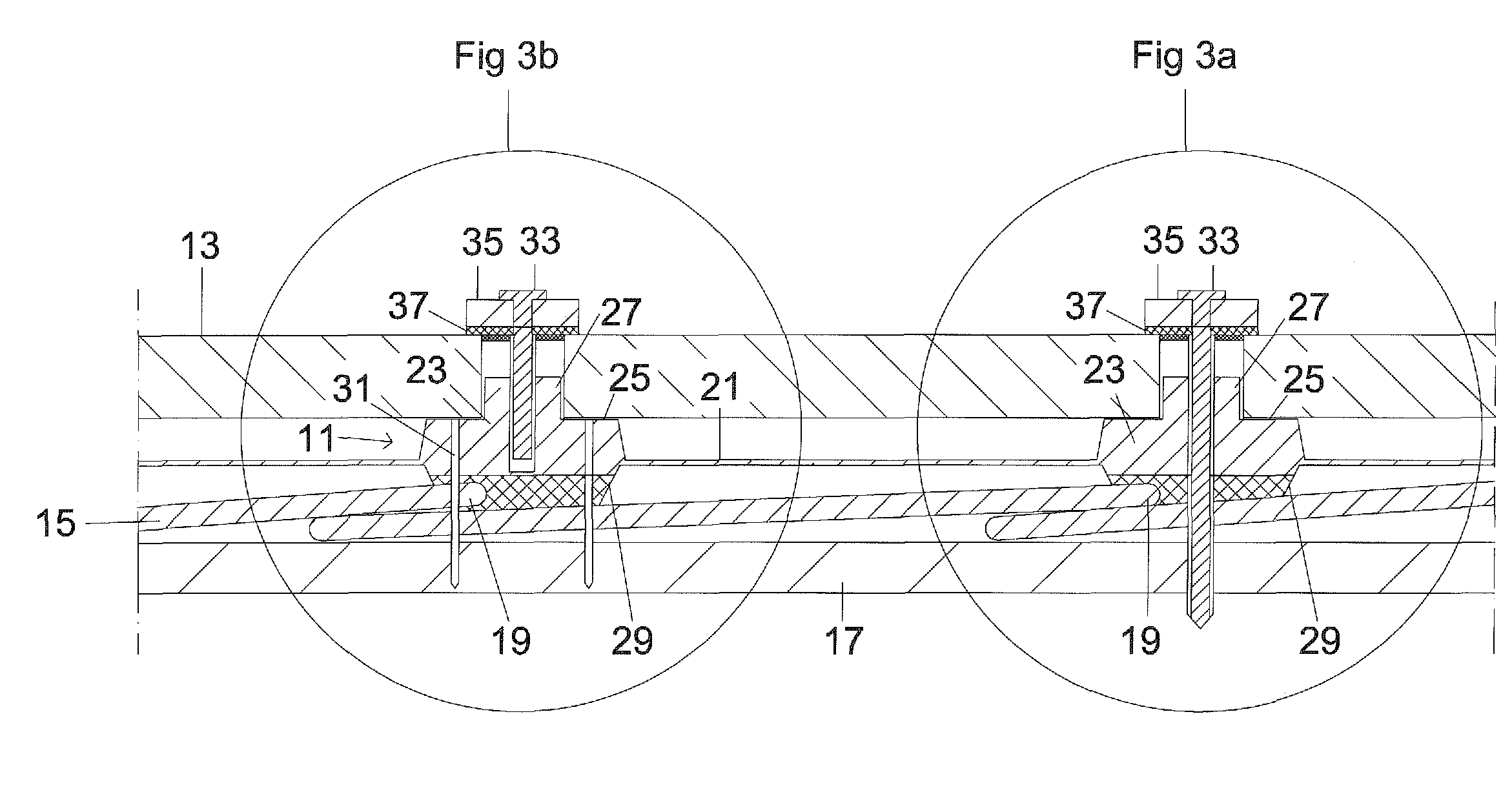
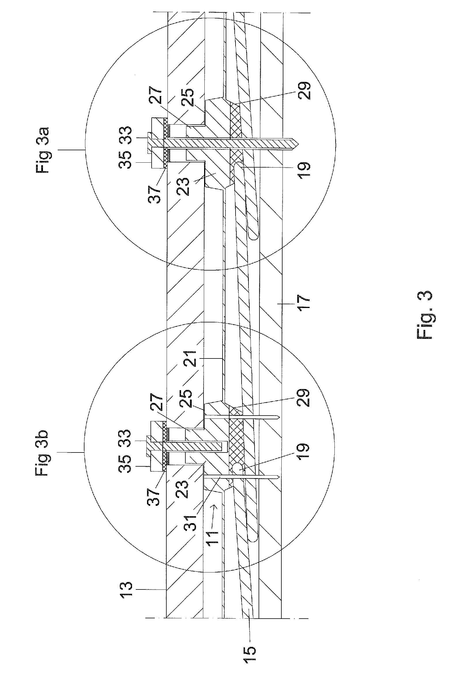
[0010]According to yet another aspect of the invention, a method for mounting a photovoltaic system having a plurality of photovoltaic modules on an uneven roof panel applied on a wooden structure with the mounting support described above includes the steps of attaching a first part of the attachment means with screws to the wooden structure, placing a second part of the attachment means on the roof panel in such a manner that the at least one strip is under tension, attaching the second part of the attachment means with screws to the wooden structure, and placing and clamping the photovoltaic modules on the supporting location or supporting surface of the attachment means. The padding hereby also seals damage to the roof panel caused by the screw-attachment to the wooden structure.
[0013]In particular, with this grid shape of the support, transverse rails are advantageously provided which connect the opposing attachment means with each other. The strips themselves should, compared to the dimensions of the attachment means, form a relatively wide longitudinal rail connecting pairs of respective attachment means with each other. This width is required so that the position of the attachment means is maintained during the screw-down operation without rotating the attachment means. However, the strip should not protrude over the width of the attachment means. If the attachment means forms, in a top view, a rectangle with edges having lengths in a range between 5 cm and 12 cm, then a width of the strips (referred above also as longitudinal rail) should be between 8 cm 12 cm and the width of the transverse rails between 1 cm and 3 cm. A different, i.e. wider, width of the transverse rail may be selected if due to the employed material a rotation lock of the attachment means during screw-down can only be attained by stiffening the grid in a second direction. A small thickness of the strips and of the transverse rails should be selected, so that they are flexible and can be easily rolled up or unrolled. A thickness between 0.5 mm to 2 mm is sufficient because the thickness is required only for adjusting the attachment means. This takes into consideration that the support should be easy and comfortable to handle, facilitating a correct orientation and positioning of the attachment means, which are only subsequently joined with the roof panel and the structure underneath.
[0017]For attaining a defined height of the PV module on the attachment means, the top side of the attachment means is provided with one or two supporting locations for the edge of the PV module, for example for the two edges of adjacent PV modules. To prevent point loads on the glass of the installed PV module, the supporting locations may advantageously be configured as supporting surfaces which are separated from each other by a separation wall operating as a stop. The separation wall prevents the two edges of adjacent PV modules, which are clamped using the same attachment means, from striking each other. The separation wall may also be formed in two parts, with one part for one photovoltaic module and another part for the other adjacent photovoltaic module. The gap between the separation parts, which can also be viewed as forming separate stops, should be as large as possible to reduce material use and weight. To facilitate the attachment means to be screwed to the wooden roof structure, the material is thinned, preferably in the central region of the attachment means, and can be easily penetrated by a self-threading screw.
[0018]The support for PV modules having a metal frame can be completely prepared in the factory, because the clamping part is narrower than the module spacing, because the module frames can also withstand point loads. An opening for penetration of the screw is also advantageous, in particular if the opening is sized so that the tip of the screw can be easily screwed in and securely held in place. With this approach, a clamping part which after installation exerts on the photovoltaic module a force directed towards the supporting surface should be added to the attachment part before. The clamping part should be somewhat narrower than the spacing between two adjacent PV modules. In this way, the clamping part can already be installed in the factory together with the screw inserted into the opening. When the PV module is placed onto the supporting surfaces of the attachment means, the clamping parts are initially rotated in a longitudinal direction parallel to the module edge and are then rotated perpendicular to the module edge after the placement of the PV module, before the screw is screwed into the wooden structure, in particular the wooden covering boards of a shingled roof, and tightened, whereby the PV module is clamped down.
[0022]As described above, with both approaches, the clamping means associated with the attachment means for clamping and affixing the photovoltaic modules can be installed at the same time the attachment means are screwed down on the wooden structure. In addition, with both variants, the grid can advantageously already be cut to size according to the available roof shape and roof size before installation, possibly already at the manufacturing site of the mounting support, before the grid is installed, thereby forestalling any inconvenience during the actual installation.

Problems solved by technology

The padding seals damage to the roof panel caused by the screw-attachment to the wooden structure.
The padding hereby also seals damage to the roof panel caused by the screw-attachment to the wooden structure.

Method used


Image

  • Roof mounting support for photovoltaic modules on uneven roofs
  • Roof mounting support for photovoltaic modules on uneven roofs
  • Roof mounting support for photovoltaic modules on uneven roofs

Examples


Embodiment Construction

[0034]Throughout all the figures, same or corresponding elements may generally be indicated by same reference numerals. These depicted embodiments are to be understood as illustrative of the invention and not as limiting in any way. It should also be understood that the figures are not necessarily to scale and that the embodiments are sometimes illustrated by graphic symbols, phantom lines, diagrammatic representations and fragmentary views. In certain instances, details which are not necessary for an understanding of the present invention or which render other details difficult to perceive may have been omitted.

[0035]Turning now to the drawing, and in particular to FIGS. 3, 3a and 3b, there is shown with the reference symbol 11a mounting support for mounting rigid photovoltaic modules 13 on an uneven roof panel. The roof panel is composed of a plurality of shingles 15 which are nailed in overlapping relationship onto a wooden substructure 17, typically with roofing nails (not shown...


PUM


Abstract

A mounting support for mounting at least one photovoltaic module having a glass pane on a top side of an, in particular, uneven roof panel includes an elongated strip which can be rolled up and / or unrolled in a roll-up / unroll direction. At least two attachment means for the photovoltaic module are disposed on the strip with a modular dimension. The bottom side of the support is provided in the region of the attachment means with a protruding padding to compensate for uneven roof areas. The top side of the attachment means is provided with a supporting location or surface for edges of the photovoltaic module. The mounting support can be packaged as a roll and attached in a simple and effective manner on uneven and rough roof shingles.

Description

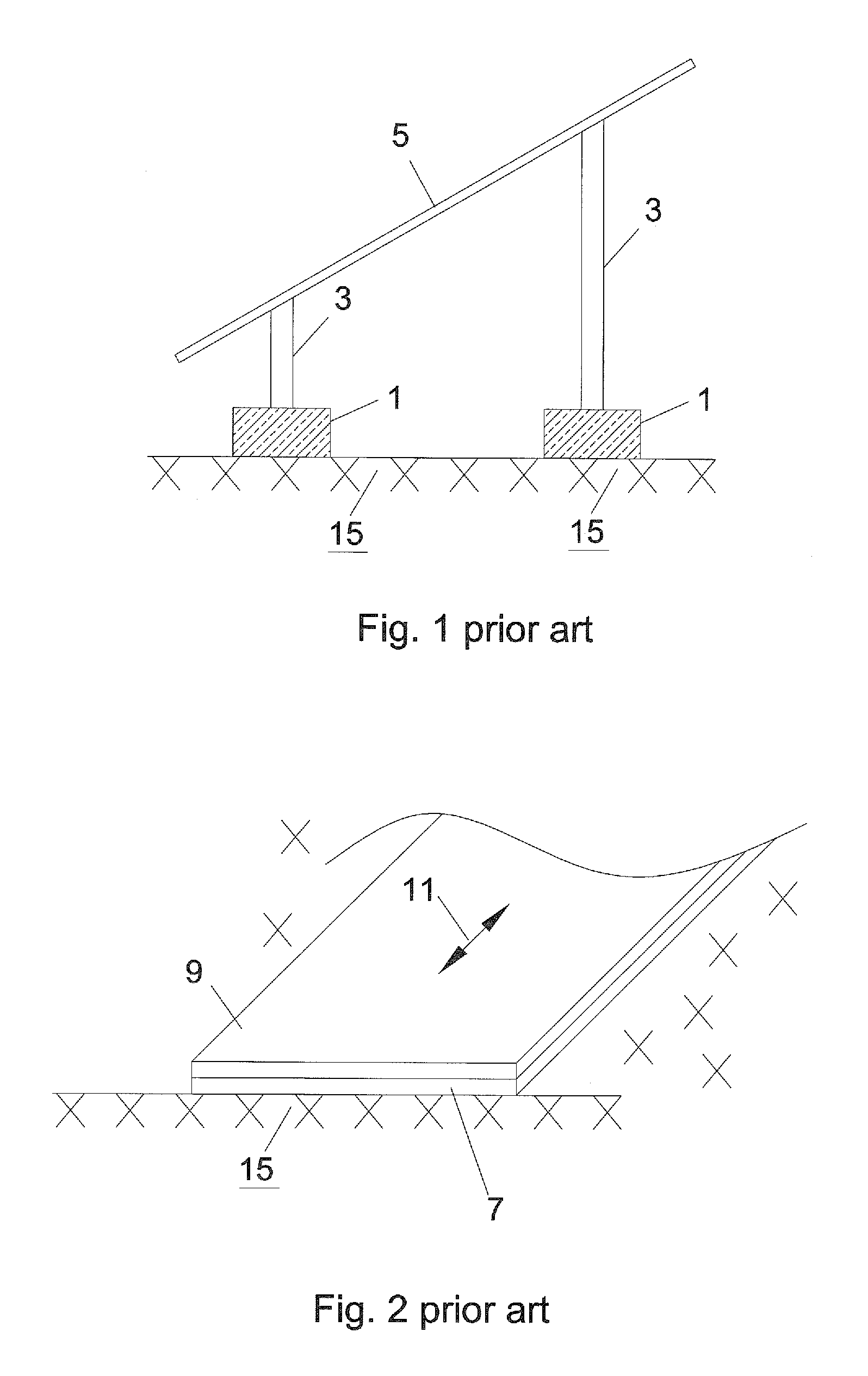
CROSS-REFERENCES TO RELATED APPLICATIONS[0001]This application claims the priority of German Patent Application, Serial No. 10 2009 037 720.4, filed Aug. 17, 2009, pursuant to 35 U.S.C. 119(a)-(d), the content of which is incorporated herein by reference in its entirety as if fully set forth herein.BACKGROUND OF THE INVENTION[0002]The present invention relates to a mounting support for mounting a photovoltaic module having a glass pane on the top side of an, in particular, uneven roof panel.[0003]The following discussion of related art is provided to assist the reader in understanding the advantages of the invention, and is not to be construed as an admission that this related art is prior art to this invention.[0004]Presently, two approaches are used for installing a solar collector system on a flat roof or an inclined roof, as described with reference to FIGS. 1 and 2. As illustrated in FIG. 1, concrete blocks 1 are placed on the roof and a corresponding support structure 3, on wh...

Claims


Application Information

Patent Timeline
Patent Type & Authority Applications(United States)
IPC IPC(8): E04D13/18E04B1/38
CPCF24J2/5203F24J2/5258F24J2002/529H02S20/23Y02B10/20Y02E10/47Y02B10/12F24S25/30F24S2025/018F24S2025/019F24S25/636Y02E10/50Y02B10/10
Inventor BECK, BERNHARD
Owner ADENSIS
Learn More