Instrumentation of Acoustic Wave Devices

a technology of acoustic waves and instruments, applied in the field of acoustic waves devices, can solve the problems of increasing error and adding more noise to the integral, and achieve the effects of increasing bandwidth, increasing error, and limiting additive nois

Inactive Publication Date: 2011-02-17
DELAWARE CAPITAL FORMATION
View PDF4 Cites 20 Cited by
  • Summary
  • Abstract
  • Description
  • Claims
  • Application Information

AI Technical Summary

Benefits of technology

[0029]Ideally the signal transfer is approximately zero outside the resonance or filter passband, allowing the integral to be taken over a spectral range significantly wider than the resonator bandwidth. Taking the integral over a frequency range that is as close as possible to the resonance filter passband limits additive noise; however leaving sufficient frequency margin compensates for variations between individual AWD's and for thermal drift. However more noise is added to the integral as the frequency is swept over increasing bandwidth, increasing the error. Thus preferably the bandwidth is selected so as to limit the noise effects while overcoming the thermal drift and the part-to-part variation between AWD's.

Problems solved by technology

However more noise is added to the integral as the frequency is swept over increasing bandwidth, increasing the error.

Method used


Image

  • Instrumentation of Acoustic Wave Devices
  • Instrumentation of Acoustic Wave Devices
  • Instrumentation of Acoustic Wave Devices

Examples


Embodiment Construction

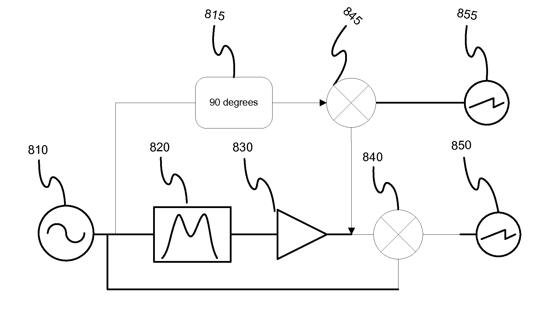
[0064]The invention will be described as it relates to the specific case of measuring a transfer function having an integral that can be readily correlated to the motional resistance response to viscosity using a shear mode AWD; however it will be readily apparent that the approach can be applied to other resonant structures and measurands having amplitude or attenuation based sensor response.

[0065]As stated above, the present invention seeks to obtain a measure of the insertion loss to represent the motional resistance change of an acoustic wave device without necessitating detailed knowledge of the resonant frequency in which this device operates at any instant.

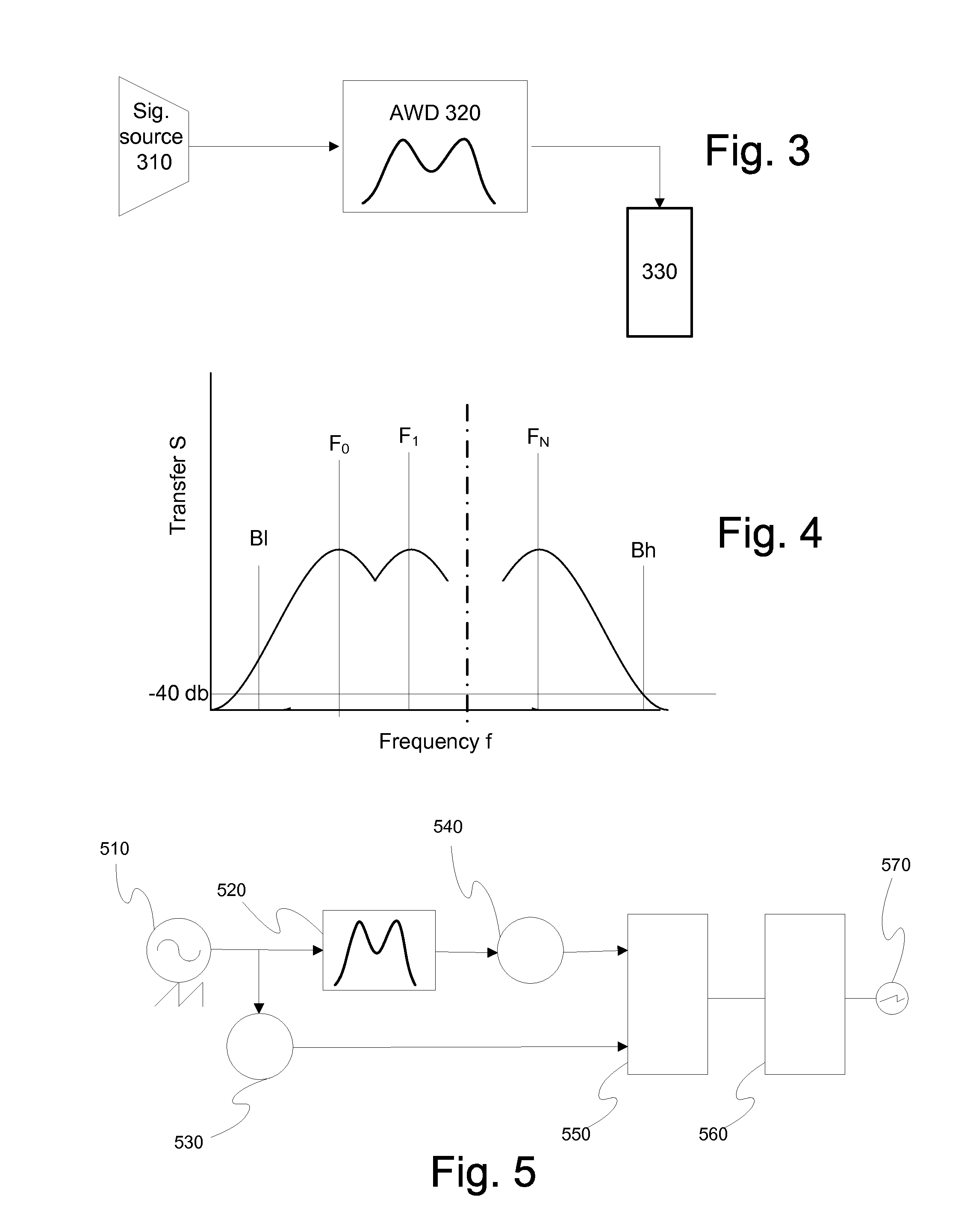
[0066]In order to overcome the errors associated with lack of exact alignment between the signal source frequency and the sensor resonance frequency, and in order to simplify instrumentation complexity, the present invention utilizes integration of a transmission function of the device. It has long been observed that the ma...


PUM

PropertyMeasurementUnit
viscoelasticaaaaaaaaaa
frequenciesaaaaaaaaaa
viscosityaaaaaaaaaa

Abstract

Characterizing material properties using a simple and inexpensive measurement circuit is disclosed. It allows measurement of the transfer function change of an acoustic wave device without necessitating detailed knowledge of the resonant frequency, by integrating the transfer function. If one examines the integral of the transfer efficiency of an acoustic wave device as the acoustic wave is damped, one sees that the magnitude of the total signal transfer decreases with increasing damping allowing derivation of the material parameters from the results of simple integration.

Description

FIELD OF THE INVENTION[0001]This application is directed generally to acoustic wave devices, and more particularly to methods, systems and devices for measuring data relating to their operating parameters in a specific environment, such as when such devices are used as sensors responding by a change in transmission efficiency to an environmental stimulus.BACKGROUND OF THE INVENTION[0002]A resonant acoustic wave device is considered herein a device comprising a crystalline material having a plurality of electrodes, and that in response to electrical power presented between at least a pair of these electrodes, provides a corresponding movement of the crystal face, and conversely, generates an electrical signal in the electrodes in response to power applied to the crystal face. Resonant acoustic wave devices support at least one resonant structure for interconverting electrical and acoustical signals at or about at least one resonant frequency. In the case of a transversal filter or de...

Claims


Application Information

Patent Timeline
Patent Type & Authority Applications(United States)
IPC IPC(8): G01N11/16
CPCG01N9/002G01N11/16G01N29/043G01N29/46G01N29/2443G01N29/348G01N29/12
Inventor ANDLE, JEFFREY C.STEVENS, DANIEL S.HASKELL, REICHL B.
Owner DELAWARE CAPITAL FORMATION
Why Eureka
Try Eureka