Self Aligning Mud Saver Valve Seat

a self-aligning, valve seat technology, applied in the direction of machines/engines, sealing/packing, borehole/well accessories, etc., can solve the problems of mud located above the pipe being removed, leaking into the environment, and devices rarely form perfect seals, so as to prevent mud leakage

Inactive Publication Date: 2011-02-17
HART TACE PARLEY +1
View PDF26 Cites 39 Cited by
  • Summary
  • Abstract
  • Description
  • Claims
  • Application Information

AI Technical Summary

Benefits of technology

[0005]A mud saver valve attached to a top drive or kelly is disclosed which has at least one floating, self aligning seat to prevent the leakage of mud when sections of pipe below the valve are removed. Such a valve has many uses other than being placed on a top drive or kelly. For example such a valve can be used with casing or drill pipe fill-up or circulating equipment to prevent leakage of mud.

Problems solved by technology

When one section of pipe is removed from the top drive or kelly, mud which is located above the pipe being removed will spill on the rig floor or into the environment.
In practice these devices seldom form a perfect seal and will allow mud to leak onto the rig floor or into the environment.

Method used


Image

  • Self Aligning Mud Saver Valve Seat
  • Self Aligning Mud Saver Valve Seat
  • Self Aligning Mud Saver Valve Seat

Examples


Embodiment Construction

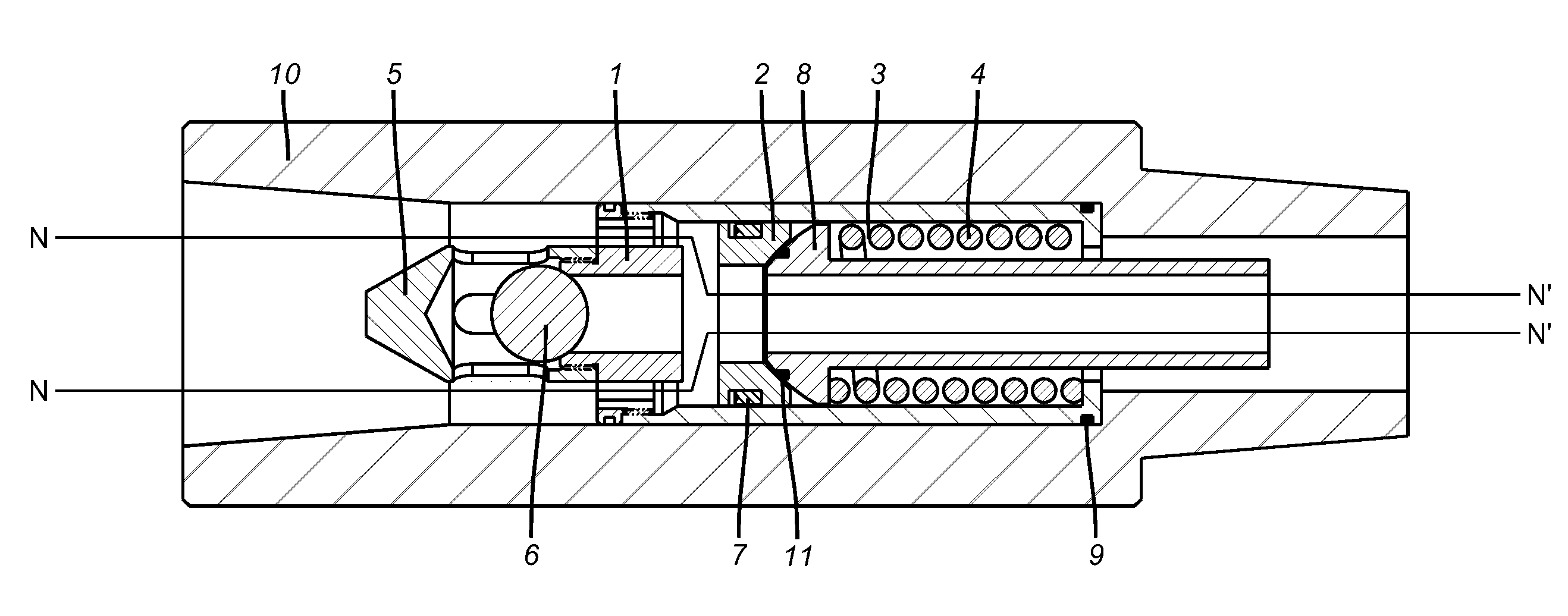
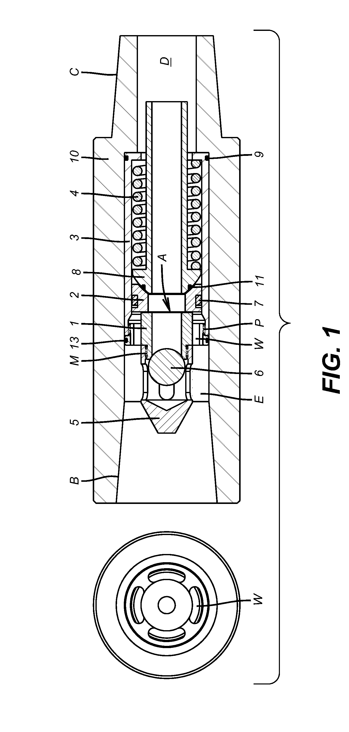
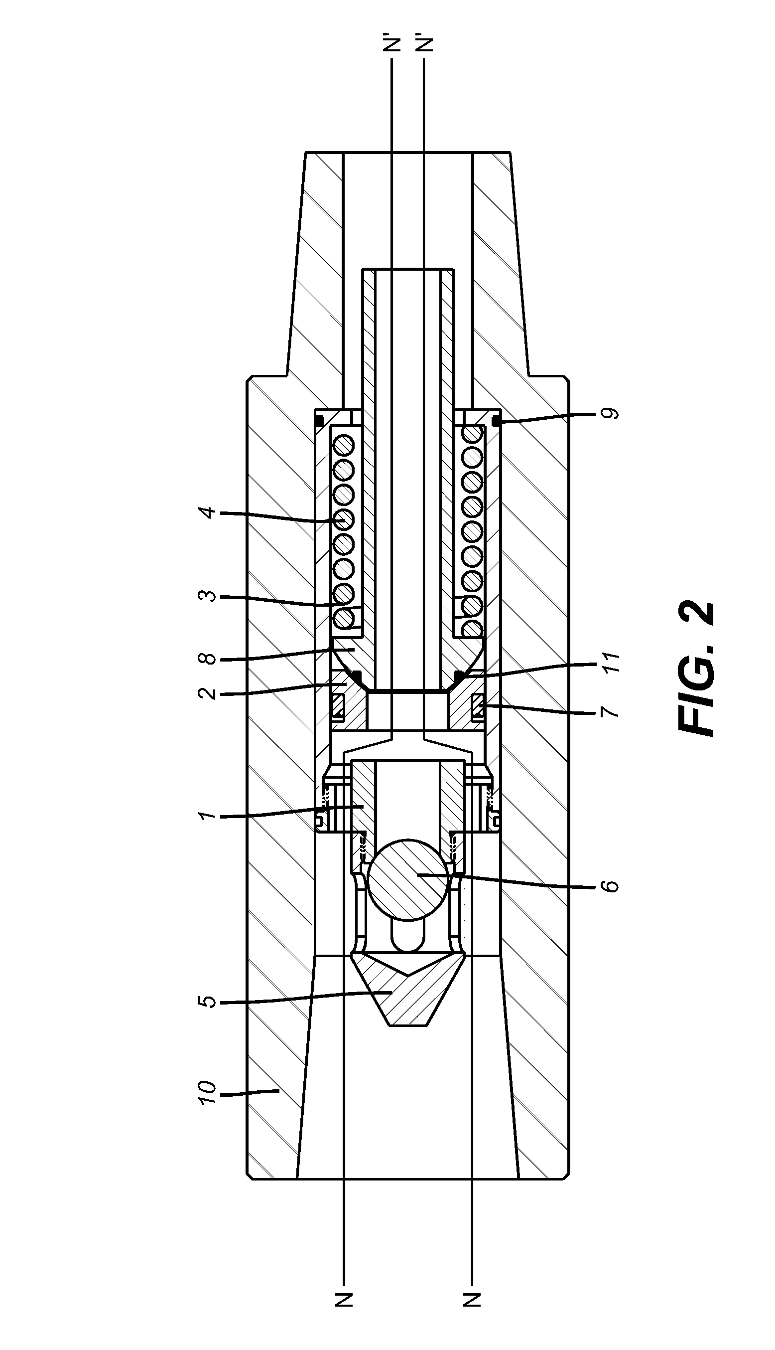
[0009]Referring to FIG. 1, the apparatus is shown inserted into a section of the drill string 10 known as a saver sub. The saver sub is attached to the lower most portion of a top drive, kelly or in a section of a fill-up and circulating device (not shown) at thread B. Drill pipe is attached to the saver sub by and at thread C. Drilling mud is pumped through the central bore E, D of the saver sub 10. When a section of drill pipe is to be added to the drill string the previous section of drill pipe attached below the saver sub is unscrewed at thread C from the saver sub and another length of drill pipe is added. When thread C is disconnected the mud in the top drive or kelly wants to flow out of the saver sub.

[0010]The valve consists of a lower seat 2 inside of a housing 3, supported by mandrel 8. Seal 9 prevents fluid from flowing between the housing 3 and saver sub 10. A seal 7 is located between the seat 2 and housing 3. Seat 2 has clearance around seal 7 so that it can relatively...


PUM


Abstract

A mud saver valve is constructed so that the valve seats self align preventing the loss of fluid when the valve is in the closed position. One or both seats can skew their longitudinal axes to get the alignment.

Description

CROSS-REFERENCE TO RELATED APPLICATION[0001]This application claims the benefit of U.S. Provisional Patent Application Ser. No. 61 / 234,528 filed Aug. 17, 2009.FIELD OF THE INVENTION[0002]The field of this invention relates to a method of preventing the leakage or spillage of mud in a drilling environment using a valve having at least on floating seat to provide self-alignment of both seats in the valve.BACKGROUND OF THE INVENTION[0003]During the process of drilling and completing a well it is necessary to run or pull the pipe into or out of the wellbore. When one section of pipe is removed from the top drive or kelly, mud which is located above the pipe being removed will spill on the rig floor or into the environment. Mud saver valves are available and are in use for the purpose of preventing such spillage. These valves have at least one seat, which is firmly attached to a rigid portion of the valve system. The second seat is firmly guided into contact with the first seat such that...

Claims


Application Information

Patent Timeline
Patent Type & Authority Applications(United States)
IPC IPC(8): E21B34/00
CPCE21B21/106Y10T137/778Y10T137/7932
Inventor HART, TACE PARLEYMULLINS, ALBERT AUGUSTUS
Owner HART TACE PARLEY
Why Eureka
Try Eureka