Composite pulse design method for large-tip-angle excitation in high field magnetic resonance imaging

Active Publication Date: 2011-02-17
GENERAL ELECTRIC CO
View PDF9 Cites 4 Cited by
  • Summary
  • Abstract
  • Description
  • Claims
  • Application Information

AI Technical Summary

Problems solved by technology

In some circumstances, the generated RF magnetic field may not provide accurate spin or rotation of nuclei, for e.g., 75° for a desired spin of 90

Method used


Image

  • Composite pulse design method for large-tip-angle excitation in high field magnetic resonance imaging
  • Composite pulse design method for large-tip-angle excitation in high field magnetic resonance imaging
  • Composite pulse design method for large-tip-angle excitation in high field magnetic resonance imaging

Examples


Embodiment Construction

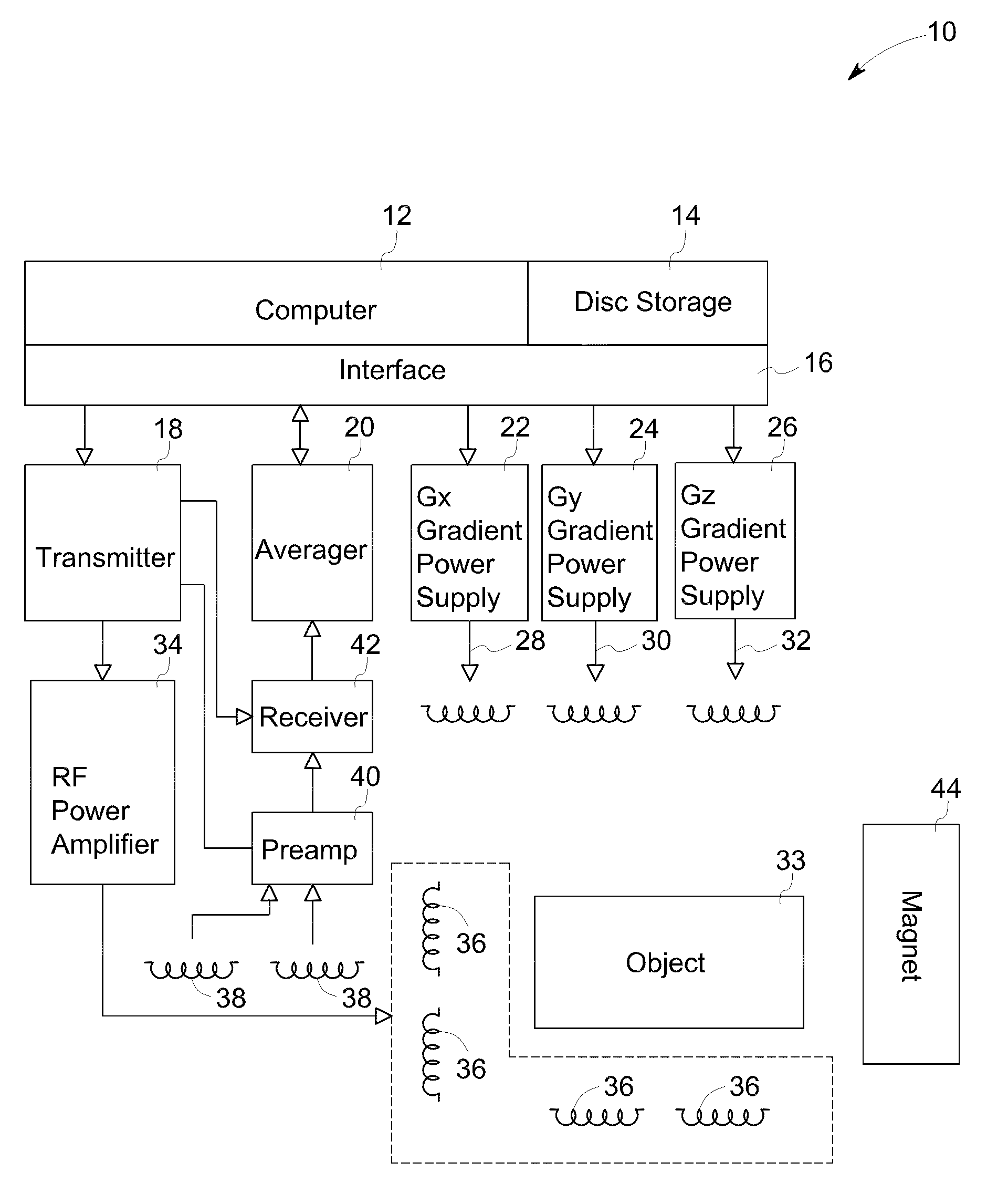
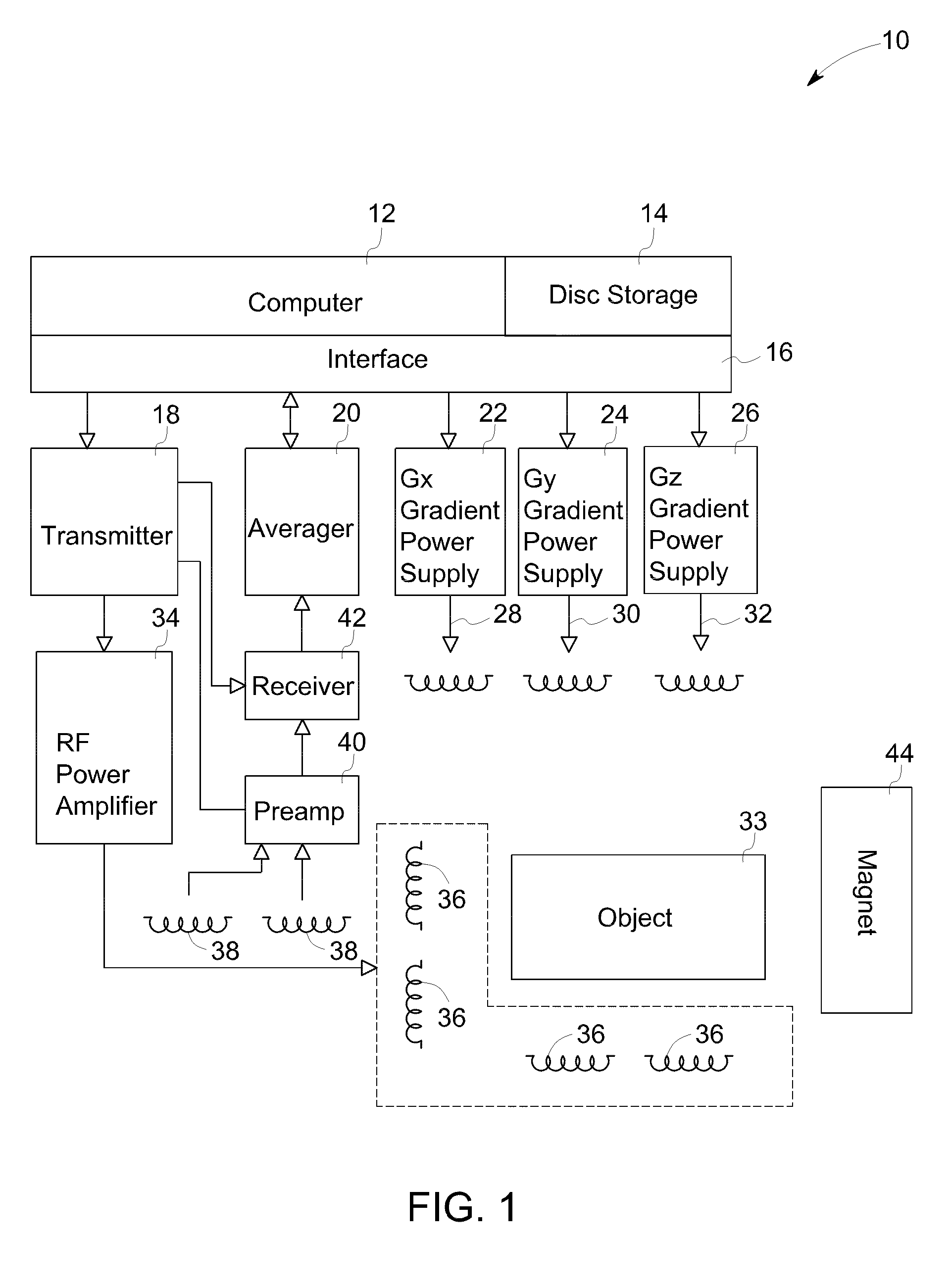
[0014]FIG. 1 is a simplified block diagram of the major components of an MRI system 10 that may incorporate embodiments of the present invention. The system 10 comprises a computer 12 which is functionally coupled to a disk storage unit 14 and an interface unit 16 and in one embodiment comprises a general purpose computer, for example. The system 10 further includes a RF transmitter 18, a signal averager 20 and gradient power supplies 22, 24 and 26 for energizing, respectively, x, y, z gradient coils 28, 30 and 32. The gradient power supplies are also coupled to computer 12 through interface unit 16.

[0015]The RF transmitter 18 is gated with pulse envelopes from computer 12 to generate RF pulses having the required modulation to excite resonance in the object 33 under study. The RF pulses are amplified in RF power amplifier 34 to levels varying from 100 watts to several kilowatts, depending on the imaging method, and applied to a plurality of transmitter RF coils 36. The higher power...


PUM


Abstract

A magnetic resonance imaging apparatus having a static magnetic field source, a plurality of radio frequency magnetic field sources and a plurality of gradient magnetic field sources for generating a gradient magnetic field is provided. The static magnetic field source generates a static magnetic field for aligning a spin vector of an object in a direction of the magnetic field and plurality of radio frequency magnetic field sources generate a radio frequency magnetic field for rotating the spin vector by an angle. The apparatus further includes a processor for generating a plurality of radio frequency excitation pulses for the plurality of radio frequency magnetic field sources and a plurality of gradient excitation pulses for the plurality of gradient magnetic field sources. The second half of each of the plurality of radio frequency excitation pulses comprises a time-reversed first half of a respective one of the plurality of radio frequency excitation pulses and the second half of each of the plurality of gradient excitation comprises a time-reversed and sign-reversed first half of a respective one of the plurality of gradient excitation pulses. The average value of each of the plurality of gradient excitation pulses is zero.

Description

STATEMENT REGARDING FEDERALLY SPONSORED RESEARCH & DEVELOPMENT[0001]This invention was made with government support under 5R01EB005307-2 awarded by National Institutes of Health. The government has certain rights in the invention.BACKGROUND[0002]The invention relates generally to a magnetic resonance imaging (MRI) system and more specifically to generation of radio frequency (RF) pulses for large tip angle excitation and spin refocusing.[0003]MRI is an imaging technique used primarily in medical settings to produce high quality images of the inside of the human body. In a MRI system nuclear magnetic moments of a portion of the body or other object to be measured are excited at specific spin precession frequencies, which are proportional to the local magnetic field. The radio-frequency signals resulting from the precession of these of signals is provided representing different regions of the volume. These are combined to produce a volumetric image of the nuclear spin density of the b...

Claims


Application Information

Patent Timeline
IPC IPC(8): G01R33/44
CPCG01R33/4836G01R33/4833
Inventor LEE, SEUNG-KYUN
Owner GENERAL ELECTRIC CO
Why Eureka
Try Eureka