
Vertebral facet joint drill and method of use

Active Publication Date: 2011-02-17
SPINAL ELEMENTS INC
View PDF101 Cites 111 Cited by
  • Summary
  • Abstract
  • Description
  • Claims
  • Application Information

AI Technical Summary

Benefits of technology

[0006]The present invention aims at addressing the clinical condition of the patient while allowing the patient to maintain mobility not common with fusion procedures. The device and procedure allow the restoration of the relative spacing between the facets within the facet joint, alleviating the bone on bone contact that is common in degenerative facet joints and often the source of pain generation, while allowing relative motion between the facets to continue post-operatively.
[0007]While other implants have been proposed with the objective of addressing facet degeneration by restoring motion, the subject device offers the benefit of requiring little to no bony resection in order for it to be placed within the spine. This advantage provides the opportunity for the patient to rely more on those anatomical structures unaffected by degeneration while providing for very little morbidity in the surgical procedure.

Problems solved by technology

Traumatic, inflammatory, and degenerative disorders of the spine can lead to severe pain and loss of mobility.
According to some studies, back and spinal musculoskeletal impairments are the leading causes of lost work productivity in the United States.
While many technological advances have focused on the spinal disc and artificial replacement or repair of the disc, little advancement in facet repair has been made.
This surgical procedure has a high rate of morbidity and can potentially lead to further clinical complications such as adjacent segment disorders.
This procedure is also not reversible.
Therefore, if the patient has an unsatisfactory result, they maybe subject to additional surgical fusion procedures.

Method used


Image

  • Vertebral facet joint drill and method of use
  • Vertebral facet joint drill and method of use
  • Vertebral facet joint drill and method of use

Examples


Embodiment Construction

A. Anatomy of the Spine

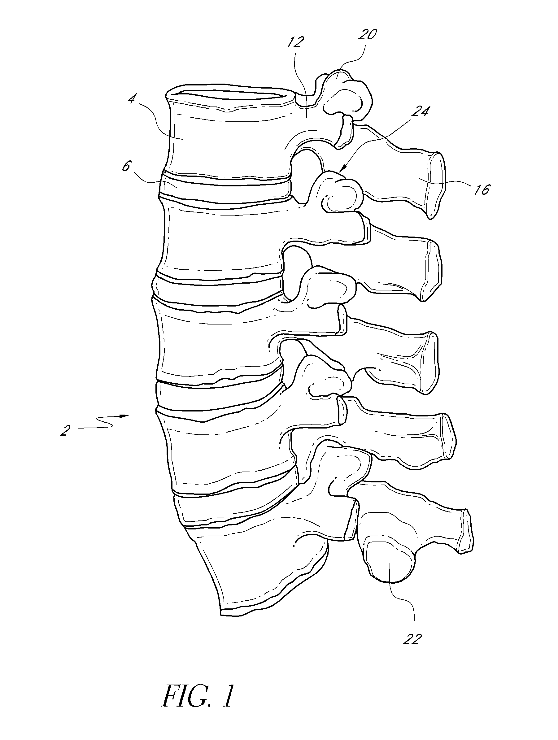
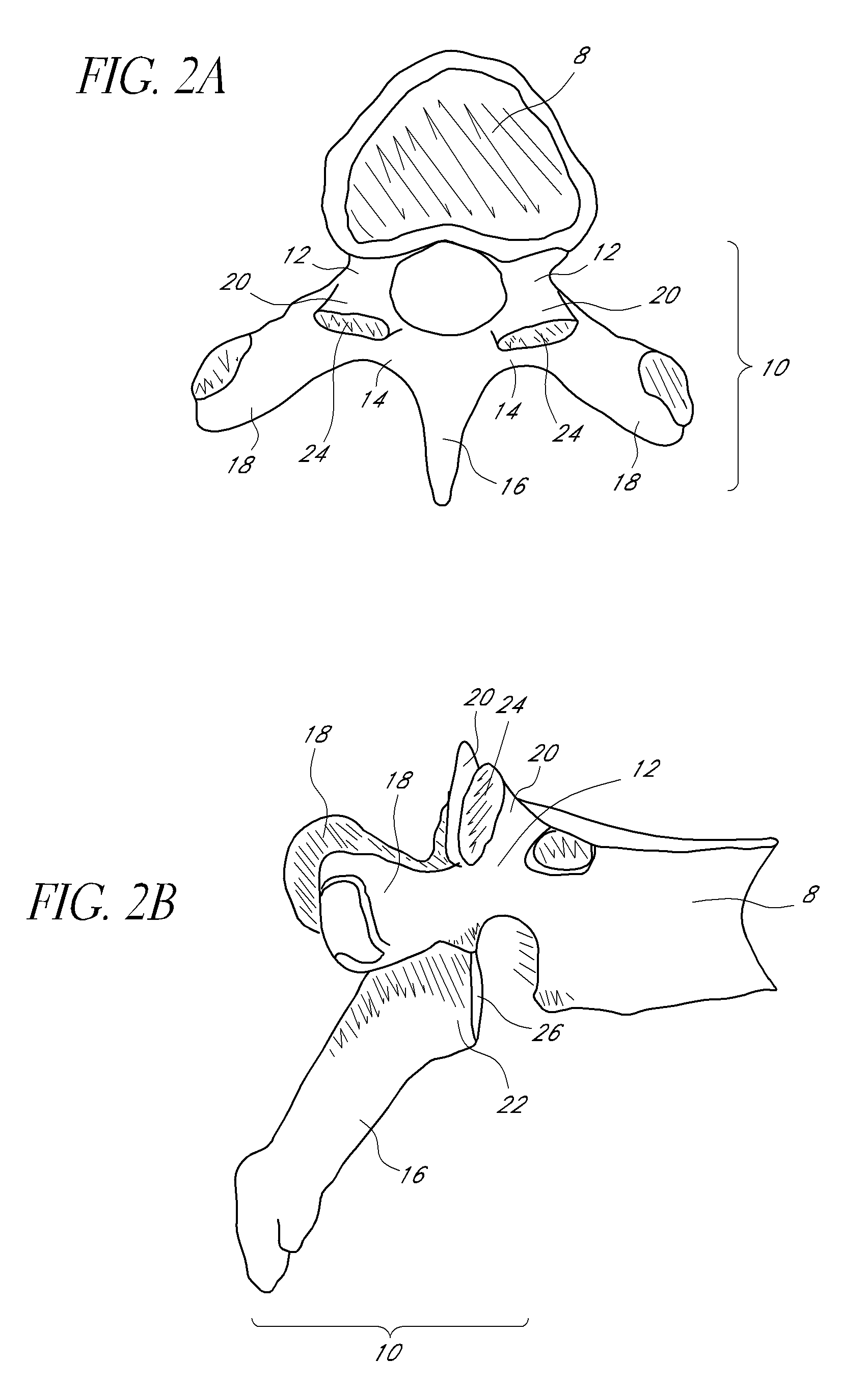
[0087]As shown in FIG. 1, the vertebral column 2 comprises a series of alternating vertebrae 4 and fibrous discs 6 that provide axial support and movement to the upper portions of the body. The vertebral column 2 typically comprises thirty-three vertebrae 4, with seven cervical (C1-C7), twelve thoracic (T1-T12), five lumbar (L1-15), five fused sacral (S1-S5) and four fused coccygeal vertebrae. FIGS. 2A and 2B depict a typical thoracic vertebra. Each vertebra includes an anterior body 8 with a posterior arch 10. The posterior arch 10 comprises two pedicles 12 and two laminae 14 that join posteriorly to form a spinous process 16. Projecting from each side of the posterior arch 10 is a transverse 18, superior 20 and inferior articular process 22. The facets 24, 26 of the superior 20 and inferior articular processes 22 form facet joints 28 with the articular processes of the adjacent vertebrae. See FIGS. 3A and 3B. The facet joints are true synovial joints with ca...


PUM


Abstract

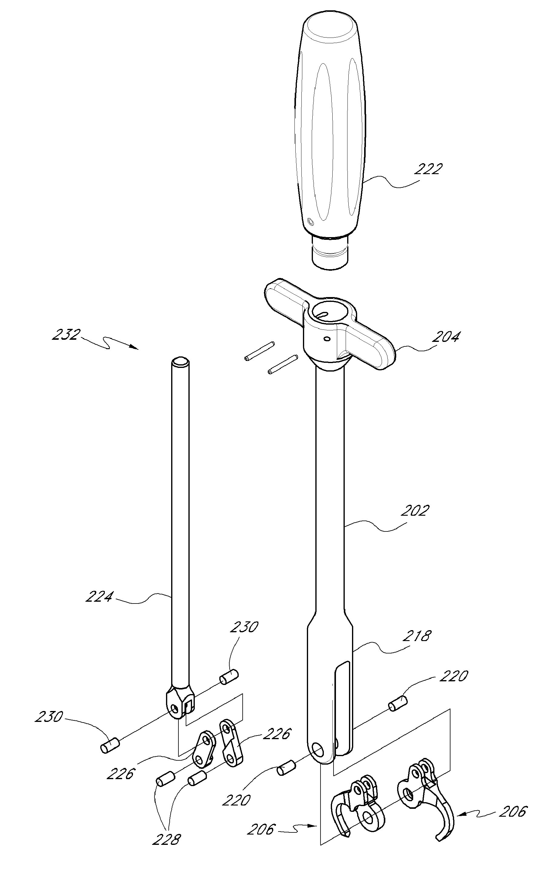
Devices and methods for creating lumens in the articular process of the vertebra are provided. An embodiment of the invention can be a tool that can cut a curved lumen through the articular process. The tool can have a lumen-forming arm with a rotating drill contained within that can be powered by a drill motor. The lumen-forming arm can be axially translated to cut a path through the articular process. Methods of using the resulting lumens to anchor or stabilize facet joint prosthesis, and also altering the spacing and motion at the facet joints of the vertebral column, are provided.

Description

CROSS-REFERENCE TO RELATED APPLICATIONS[0001]The present application is a continuation-in-part of U.S. application Ser. No. 12 / 035,366 filed on Feb. 21, 2008, which claims priority under 35 U.S.C. §119(e) to U.S. Provisional Application No. 60 / 891,159 filed on Feb. 22, 2007, the disclosures of which are incorporated by reference herein in their entireties.TECHNICAL FIELD[0002]The present invention relates to devices for creating holes in the articular processes of the vertebra and the surgical method of using the devices for creation of holes and the use of the holes with facet joint prosthesis retainers.BACKGROUND[0003]Traumatic, inflammatory, and degenerative disorders of the spine can lead to severe pain and loss of mobility. According to some studies, back and spinal musculoskeletal impairments are the leading causes of lost work productivity in the United States. Pain as a result of some type of spinal impairment may have its source in a variety of pathologies or clinical condi...

Claims


Application Information

Patent Timeline
IPC IPC(8): A61B17/16
CPCA61B17/1608A61B17/1642A61B17/7064A61B17/562A61B17/1671A61B17/1615A61B17/1637
Inventor BLAIN, JASONKOVACH, ERIC
Owner SPINAL ELEMENTS INC
Learn More