Method and program for identifying errors

Active Publication Date: 2011-02-17
OKUMA CORP
View PDF8 Cites 31 Cited by
  • Summary
  • Abstract
  • Description
  • Claims
  • Application Information

AI Technical Summary

Benefits of technology

guration, in addition to the above advantageous effects of the identification method according to the first aspect of the invention, while maintaining the accuracy, a more simple identification method can be realized.
According to an alternative preferred embodiment of the aforementioned identification method, the approximating step may comprise determining a radius of the circular arc by measuring a distance from a center of the rotational axis to the plurality of measured values, and the error calculating step may comprise calculating the geometric errors in regard to the rotational axis from first-order components of the circular arc.
With this configuration too, in addition to the above advantageous effects of the identification method according to the first aspect of the invention, while maintaining the accuracy, a more simple identification method can be realized.
According to another preferred embodiment of the aforem

Problems solved by technology

With these configurations of the aforementioned identification method and program, not only geometric errors in regard to the rotational axes but also geometric errors in regard to the translational axes ca

Method used


Image

  • Method and program for identifying errors
  • Method and program for identifying errors
  • Method and program for identifying errors

Examples


Embodiment Construction

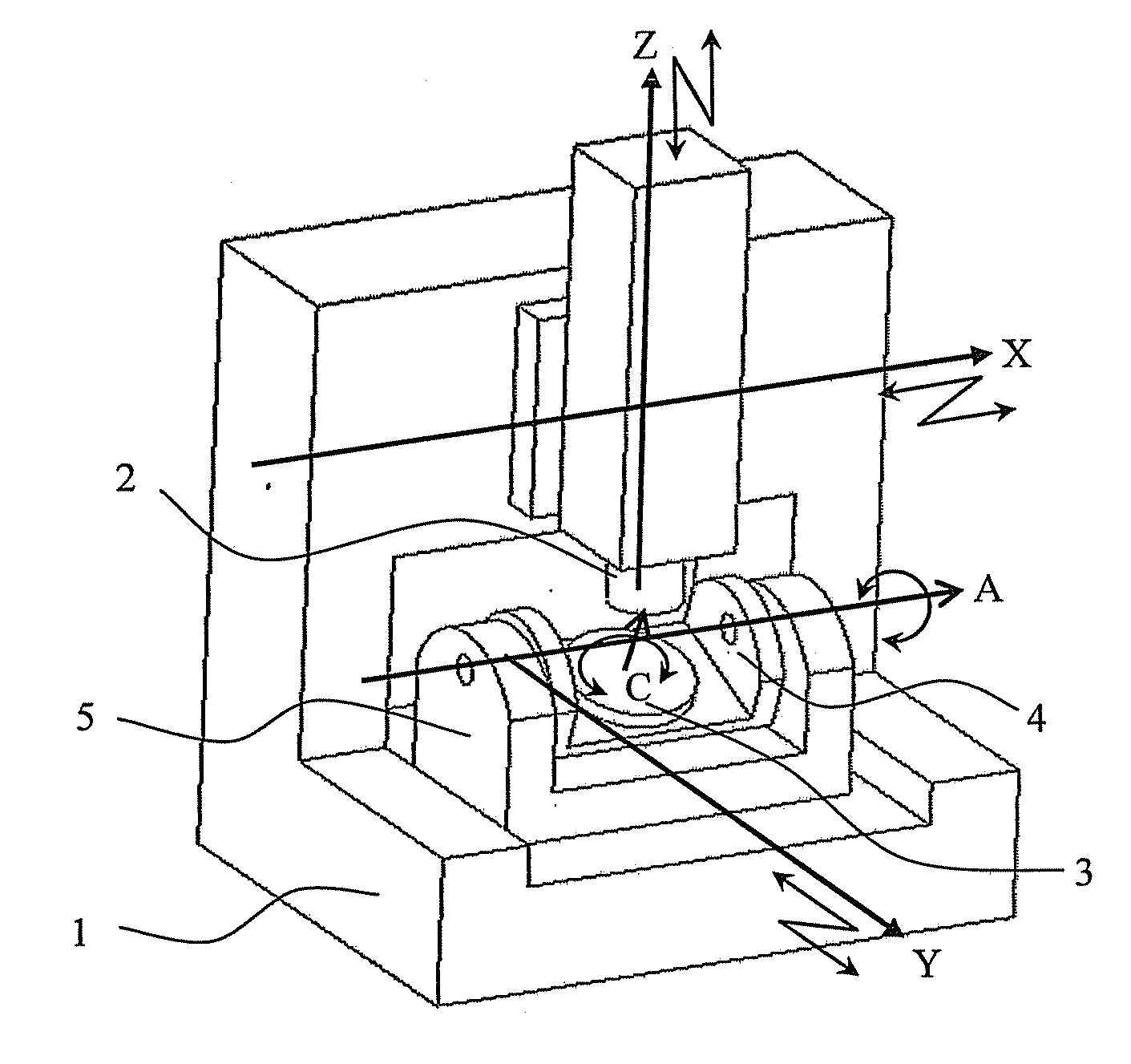
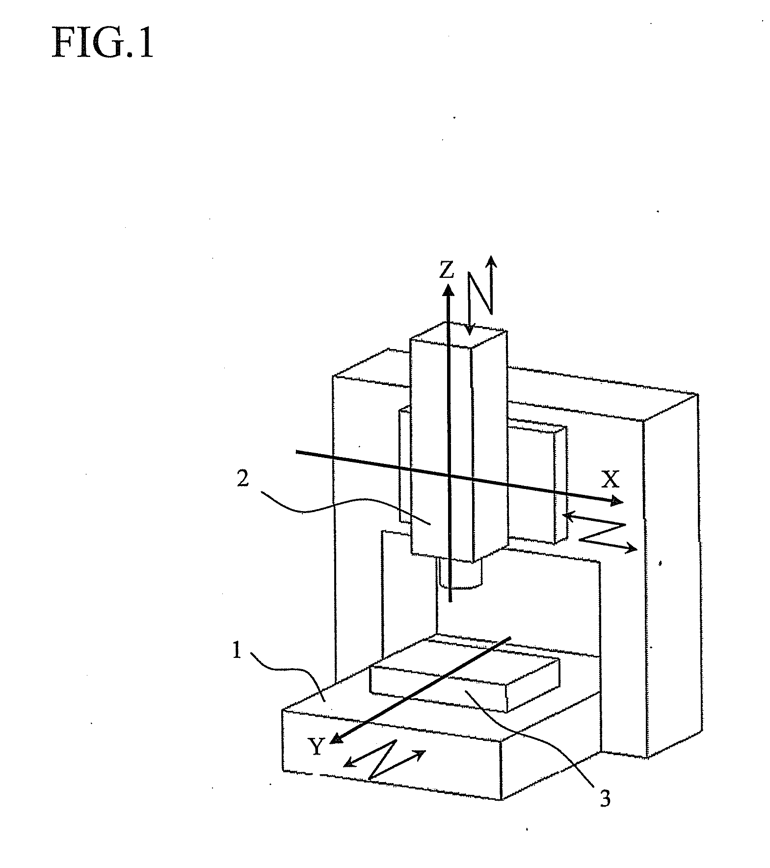
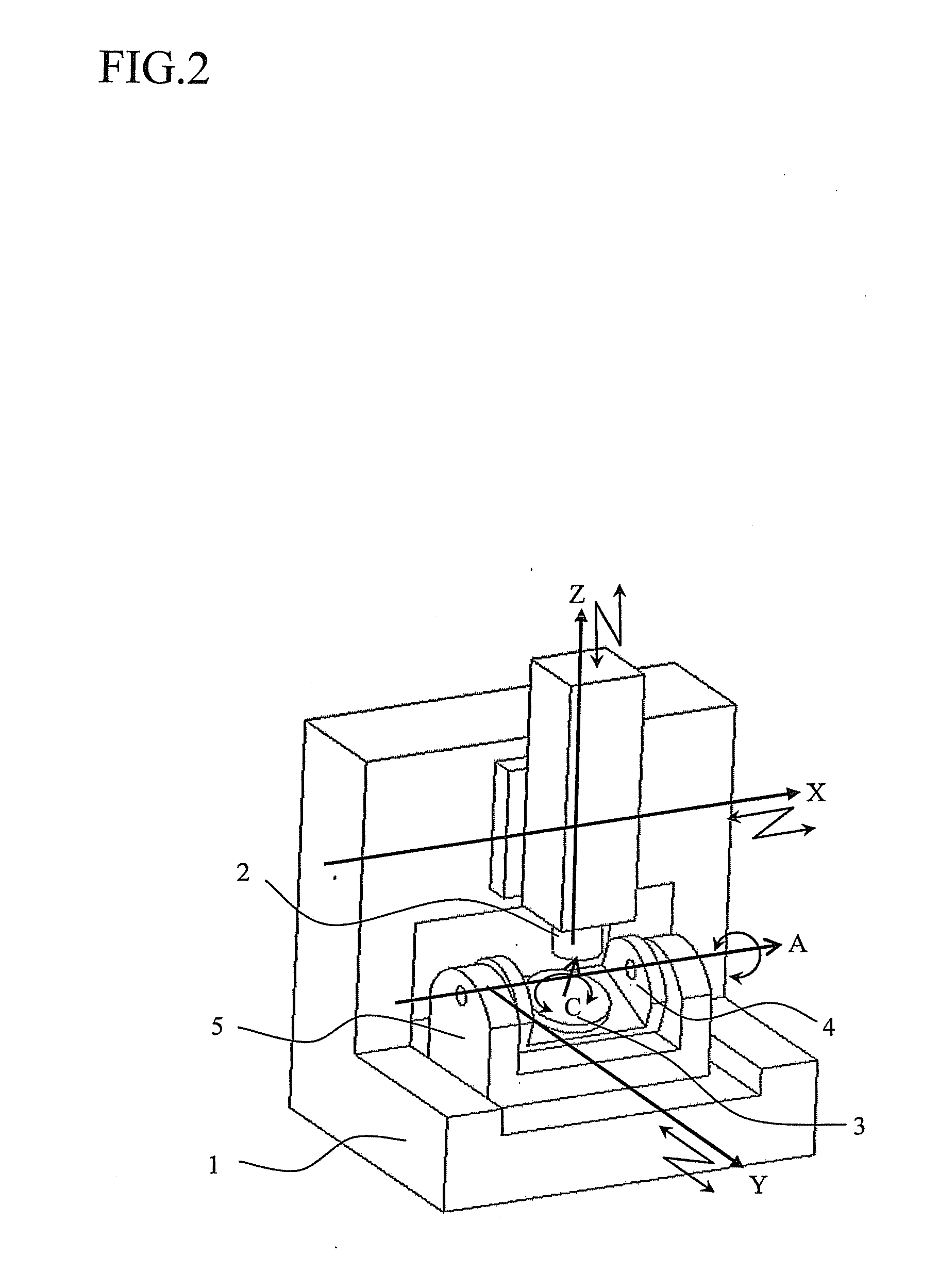
With reference to the accompanying drawings where necessary, a method for identifying errors of a five-axis control machining center shown in FIG. 2, which is one exemplary embodiment of the present invention, using a computer (i.e., controller (not shown)) will be described below. The computer may be a numerical controlling device for the five-axis machine, a separate computer connected to the numerical controlling device, or the combination thereof. It is to be noted that the present invention is not limited to the following specific embodiment.

First, geometric errors will be described. A total of six component error parameters (i.e., δx, δy, δz, α, β, γ) are defined as geometric errors; that is, relative translational errors in three directions and relative rotational errors in three directions between the axes. In the case of the five-axis machine as shown in FIG. 2, axes are related from the workpiece to the tool in the order of the C-axis, the A-axis, the Y-axis, the X-axis, a...


PUM


Abstract

A method for identifying geometric errors with respect to at least two translational axes and at least one rotational axis of a machine using a control device is disclosed. The method comprises the steps of: measuring positions of a jig in three-dimensional space using a position measurement sensor, wherein a measurement is carried out when the jig being indexed around the rotational axis by a plurality of angles is located at the positions; approximating a plurality of measured values of the positions measured in the measuring step to a circular arc; and calculating an error in regard to a center position of the rotational axis and/or a tilt error in the rotational axis, and tilt errors in the translational axes, based on the circular arc resulting from the approximating step.

Description

This application claims the entire benefit of Japanese Patent Application Number 2009-186735 filed on Aug. 11, 2009, the entirety of which is incorporated by reference.BACKGROUND OF THE INVENTION1. Field of the InventionThe present invention relates to a method and a program for identifying geometric errors of a machine having translational and rotational drive axes.2. Description of Related ArtAs an example of a machine having translational and rotational drive axes, there is known a machine tool for processing parts or metal molds. Such a machine tool can process a workpiece into a desired shape by a material removal process including relative movements of both or either of a tool and a workpiece while rotating the tool or the workpiece.As an example of this machine tool, FIG. 1 shows a schematic view of a three-axis control machining center (three-axis machine) having three translational axes. A spindle head 2 is allowed to make a translational movement with 2 degrees of freedom ...

Claims


Application Information

Patent Timeline
IPC IPC(8): G01B5/008
CPCG01B21/045B23Q17/22B23Q1/5437
Inventor MATSUSHITA, TETSUYA
Owner OKUMA CORP
Why Eureka
Try Eureka