
Insulating construction panel with photovoltaic module

a technology of photovoltaic modules and construction panels, which is applied in the direction of photovoltaic supports, sustainable buildings, pv power plants, etc., can solve the problems of unattractive and unattractive bulkiness of traditional crystalline photovoltaic modules, high installation cost and time consumption of photovoltaic modules to pre-existing structures, and reduce the overall cost and time of construction. , to achieve the effect of improving the power generation efficiency of crystalline photovoltaic modules

Inactive Publication Date: 2011-02-24
POWER NANOTECH
View PDF5 Cites 24 Cited by
  • Summary
  • Abstract
  • Description
  • Claims
  • Application Information

AI Technical Summary

Benefits of technology

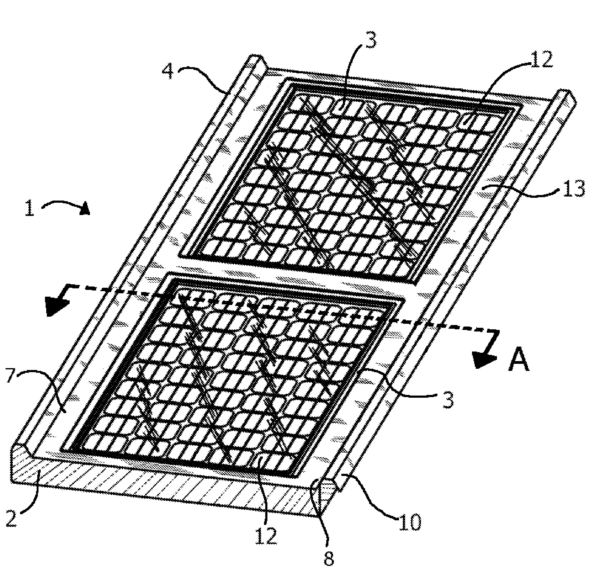
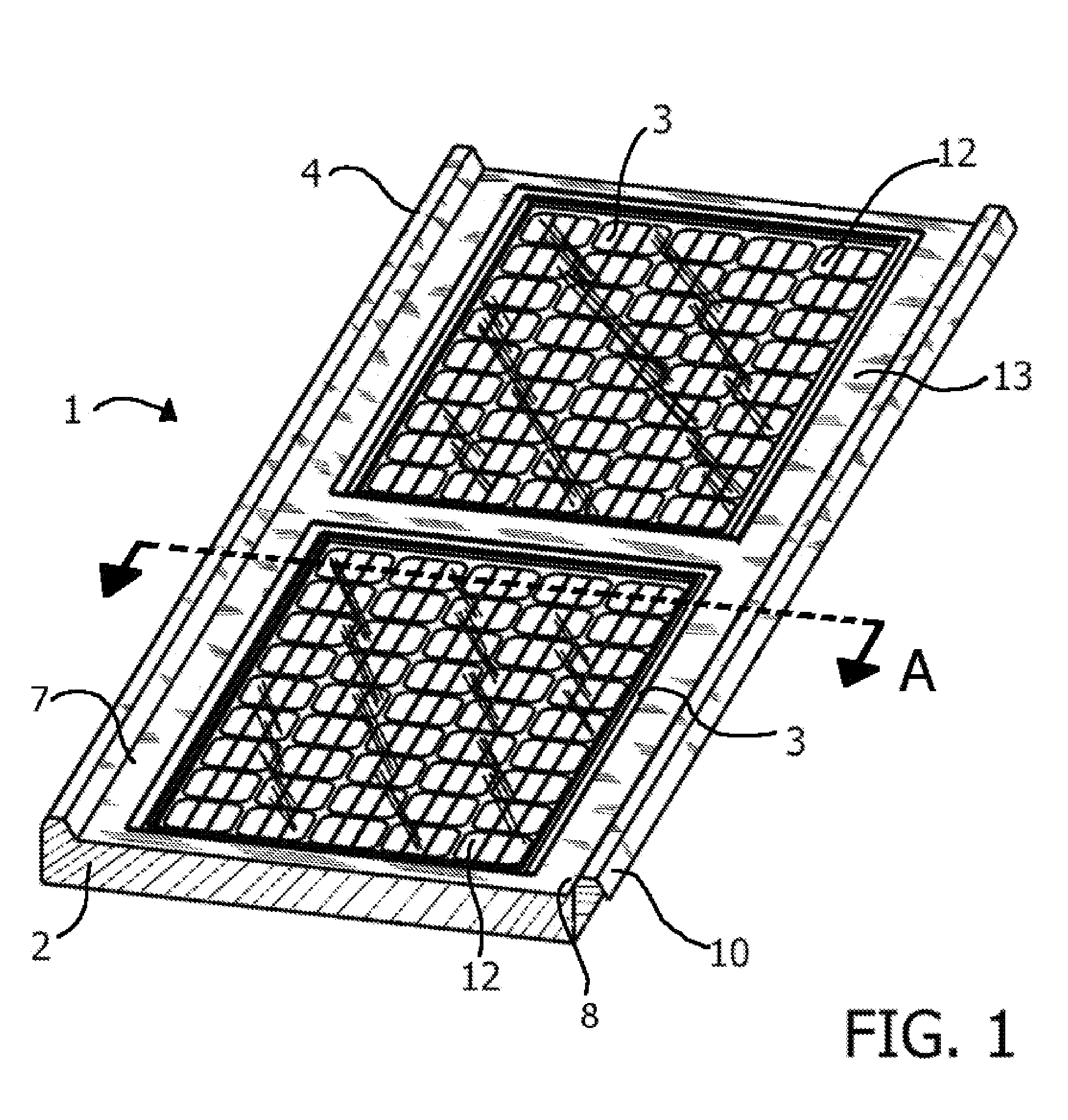
[0005]Described herein is an insulating construction and solar panel in which a crystalline photovoltaic module is fitted within an opening in an insulating core that is covered by a rigid skin. A translucent pane covers the outer surface of the crystalline photovoltaic module, and the translucent pane is sealed to the rigid skin so that the crystalline photovoltaic module is protected from environmental elements. The insulating construction and solar panel is preferably pre-fabricated before transport to a construction site, and installation requires little more than interconnecting one panel to another. This reduces the overall cost and time of construction. Further, because the crystalline photovoltaic module is fitted within the insulating core of the panel, the need for separate installation of a solar panel to the structure is eliminated, and the construction panel need not be separately insulated during installation. Fitting the crystalline photovoltaic module within the insulating core of the panel further provides the aesthetic benefits of a thin photovoltaic module installation with the improved power-generation efficiency of a crystalline photovoltaic module. Also, because the crystalline photovoltaic module is sealed within the panel during initial fabrication, the panel is not made vulnerable to leaks in the way that a later-installed, separate solar panel is.
[0009]The insulating core defines an opening into which a crystalline photovoltaic module is fitted. Preferably, the shape of the opening conforms to the shape of the crystalline photovoltaic module. In some embodiments, the opening extends all the way through the insulating core, such that the inner surface of the crystalline photovoltaic module is exposed to the interior of the structure. This embodiment is ideal for warmer environments, so that the inner surface of the crystalline photovoltaic module is well ventilated, thus minimizing the risk that the crystalline photovoltaic module will overheat or reach temperatures at which the crystalline photovoltaic module is inefficient in its solar-energy-to-power generation.

Problems solved by technology

However, installing photovoltaic modules to pre-existing structures is often expensive and time consuming.
Further, installing photovoltaic modules to structures can lead to leaks at mounting points, particularly when the photovoltaic modules are mounted to roofs, and can require the installation of additional structural support, given the heft of the photovoltaic module installed.
The bulkiness of traditional crystalline photovoltaic modules is also undesirable and unattractive.
Such bulky installations on roofs can further inhibit snow shedding, raising the risk that snow will accumulate undesirably and lead to roof damage or collapse.
However, thin film type solar cells are less efficient in solar power generation than the traditional crystalline photovoltaic modules.
Further, like crystalline photovoltaic modules, the thin film type solar cells still require installation onto a pre-existing structure, such as a roof, and therefore raise the risk of leaks and other structural damage.
However, while the use of pre-fabricated metal panels reduces the overall cost of construction of roofs and other structures, adding solar panels to such structures has still required the mounting of separate solar panel modules.
These installations lead to the same problems found with installing solar panels to more traditionally-constructed structures.

Method used


Image

  • Insulating construction panel with photovoltaic module
  • Insulating construction panel with photovoltaic module
  • Insulating construction panel with photovoltaic module

Examples


first embodiment

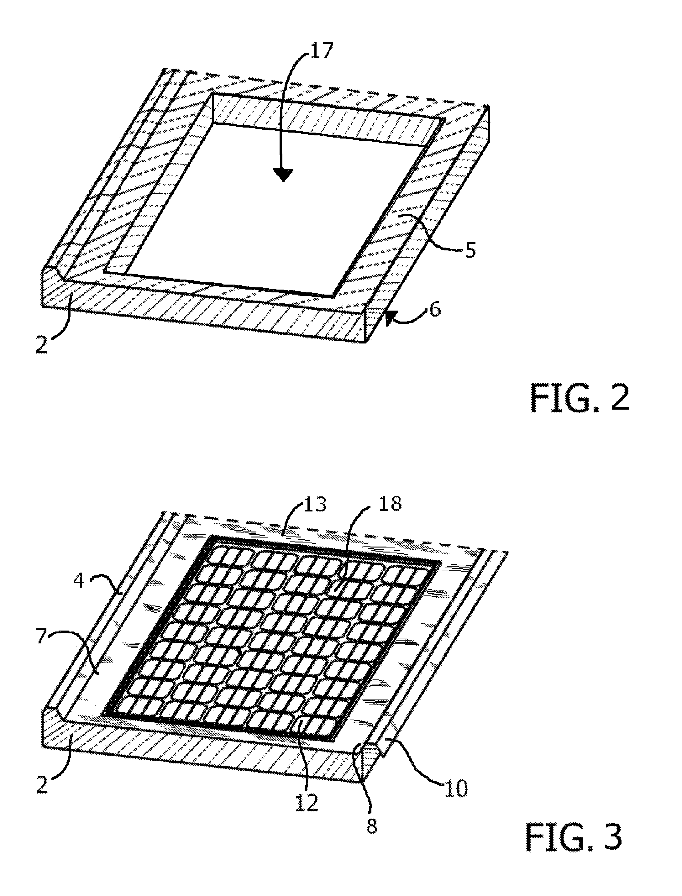
[0034] depicted in FIGS. 1 through 4 and 7, the opening 17 defined by the insulating core 2 extends from the top surface 5 of the insulating core 2 through to the bottom surface 6 as shown in FIGS. 2 and 4. The crystalline photovoltaic module 12, fitted within the insulating core 2, therefore, is non-insulated at its outer surface 18 and inner surface 19. Such an embodiment would be preferable in warmer environments as the non-insulated inner surface 19 can be ventilated from being exposed to the interior of the structure in which it is incorporated. In some such embodiments, the height of the crystalline photovoltaic module 12 essentially matches the height of the insulating core 2, such that, when the crystalline photovoltaic module 12 is fitted within the opening 17 of the insulating core 2, the outer surface 18 of the crystalline photovoltaic module 12 is essentially flush with the top surface 5 of the insulating core 2 and the inner surface 19 of the crystalline photovoltaic mo...

third embodiment

[0035] depicted in FIGS. 1, 3, and 8, the opening 17 defined by the insulating core 2 extends from the top surface 5 into the interior of the insulating core 2, but not through to the bottom surface 6. As such, when the crystalline photovoltaic module 12 is fitted within the insulating core 2, the inner surface 19 is covered and therefore insulated by the insulating core 2. Such an embodiment would be preferably in cooler environments where overheating of the crystalline photovoltaic module 12 is not a large concern.

second embodiment

[0036] depicted in FIGS. 1 through 3, 5 and 6, the insulating construction and solar panel 1 further includes at least one adjustable insulating shutter 11 connected to the insulating core 2. The adjustable insulating shutter 11 is configured so that it can be selectively moved from a closed position, such as that shown in FIG. 6, to at least one open position, such as that shown in FIG. 5. In the closed position (FIG. 6), the adjustable insulating shutter 11 covers and insulates the inner surface 19 of the crystalline photovoltaic module 12. Thus, the closed position (FIG. 6) is ideal for use during instances of cooler environmental conditions. In the open positions, such as that shown in FIG. 5, the inner surface 19 of the crystalline photovoltaic module 12 is at least partially uncovered so as to leave the inner surface 19 of the crystalline photovoltaic module 12 at least partially exposed. The open positions are ideal for use during instances of warmer environmental conditions,...


PUM


Abstract

Disclosed is an insulating construction and solar panel comprising an insulating core that defines at least one opening. A rigid skin covers the insulating core and defines a ridge extending along a first edge and a channel extending along a second edge. A crystalline photovoltaic module is fitted within the opening, and a translucent pane covers the outer surface of the crystalline photovoltaic module. The insulating construction and solar panel is configured to connect to a second and third insulating construction and solar panel by interconnecting the corresponding ridges and channels.

Description

FIELD OF THE INVENTION[0001]The present insulating construction panel with photovoltaic module relates generally to solar electricity generation and more specifically to the integration of solar-electricity-generating modules into structures.BACKGROUND OF THE INVENTION[0002]Photovoltaic modules are used to generate usable power from solar energy. Use of such modules to provide power to structures, such as homes and office buildings, has become very popular. However, installing photovoltaic modules to pre-existing structures is often expensive and time consuming. Further, installing photovoltaic modules to structures can lead to leaks at mounting points, particularly when the photovoltaic modules are mounted to roofs, and can require the installation of additional structural support, given the heft of the photovoltaic module installed. The bulkiness of traditional crystalline photovoltaic modules is also undesirable and unattractive. Such bulky installations on roofs can further inhi...

Claims


Application Information

Patent Timeline
Patent Type & Authority Applications(United States)
IPC IPC(8): H01L31/042
CPCE04D3/352H01L31/048H02S20/23Y02E10/50Y02B10/12Y02B10/10
Inventor LEVINE, BART
Owner POWER NANOTECH
Learn More