Touch sensing apparatus and method

Inactive Publication Date: 2011-02-24
SILICON INTEGRATED SYSTEMS
View PDF5 Cites 171 Cited by
  • Summary
  • Abstract
  • Description
  • Claims
  • Application Information

AI Technical Summary

Benefits of technology

[0006]An objective of the present invention is to provide a touch sensing apparatus being able to disperse noise interferences of different frequencies.

Problems solved by technology

However, the sensing elements are sensitive to noises.
Therefore, the values of the sensing signals are easily influenced so that it is difficult to accurately distinguish the touch position and determine the touch strength.
Therefore, the touch panels may be interferences by various noises such as 1/f noise, white noise, power noise, 50/60 Hz noise, microwave (e.g. infrared, blue tooth etc.) noise, backlight noise or the

Method used


Image

  • Touch sensing apparatus and method
  • Touch sensing apparatus and method
  • Touch sensing apparatus and method

Examples


first embodiment

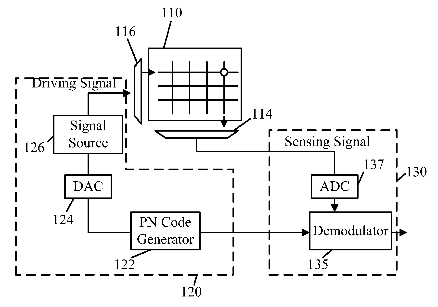
[0036]FIG. 5 is a schematic diagram showing a touch sensing apparatus 100 in accordance with the present invention. The touch sensing apparatus 100 (e.g. a touch panel) includes a sensing array 110 having a number of conductors intersecting as columns and rows, each intersection (i.e. a node) is provided with a sensing element (not shown) such as a capacitor or a resistor. In the present embodiment, the touch sensing apparatus 100 includes a driving circuit 120 and a sensing circuit 130. The driving circuit 120 has a modulation signal generator, which is implemented by a PN code generator 122 in the present embodiment. The PN code generator 122 randomly generates a code as a modulation signal, which is digital. The code is converted into an analog code waveform by a digital-to-analog converter (DAC) 124. The analog code waveform is used to modulate a driving signal, which can be a voltage or current signal, provided by a signal source 126. The PN code modulated driving signal is sen...

third embodiment

[0043]FIG. 12 is a schematic diagram showing a touch sensing apparatus 300 in accordance with the present invention. In this embodiment, the sensing apparatus 300 is similar to the sensing apparatus 100 in FIG. 5. The only difference is that the modulation signal generator is implemented by a periodic wave generator (e.g. a square wave or sine wave generator) 322 in the present embodiment. It is noted that DAC and ADC are omitted herein for the sake of simplification. A periodic wave (e.g. square wave) provided by the periodic wave generator 322 is used as a modulation signal to modulate a voltage or current signal of a signal source 326 to generate a modulated driving signal to driving a row of a sensing array 310 through a multiplexer 316. A specific column is detected through a multiplexer 314 and a sensing signal of a node, which is the intersection of the driven row and the detected column, is obtained. The sensing signal is demodulated with the same periodic wave by a demodula...

fourth embodiment

[0045]FIG. 14 is a schematic diagram showing a touch sensing apparatus 400 in accordance with the present invention. The touch sensing apparatus 400 is similar to the touch sensing apparatus 200 in FIG. 10, except that the PN code generators are all replaced by periodic wave generators 432, 442, . . . , 492. The periodic wave generators 432, 442, . . . , 492 can be implemented by square wave generators or sine wave generators, for example. The periodic wave generators 432, 442, . . . , 492 respectively provide periodic waves (e.g. square waves or sine waves) of different frequencies f-1, f-2, . . . , f-n to modulate a signal provided by a signal source 426 so as to generate different driving signal for driving rows of a sensing array 410. It is preferred that the different frequencies are separated from each other by an interval of at least 10 kHz. The determination of the interval relates the time of measurement. The longer the time to measure a column is, the narrower the noise ba...


PUM


Abstract

A touch sensing apparatus utilizes the characteristics of orthogonal vectors is disclosed. A random spread spectrum (RSS) signal or a periodic wave is used to modulate a driving signal so as to driving a row of a sensing array, and the RSS signal or periodic wave is also use to extract touch information of a node from a sensing signal measured from a column of the sensing array. The node is an intersection of the driven row and the measured column. When different RSS signals and/or periodic waves are used to drive multiple rows simultaneously, multipoint touching information can be obtained from the same sensing signal at the same time by respectively using the RSS signals and/or periodic waves to extract touching information of multiple points which are the intersections of the driven rows and the measured column.

Description

TECHNICAL FIELD OF THE INVENTION[0001]The present invention relates to touch sensing, more particularly, to touch sensing apparatuses with low noise and being able to perform multipoint touch sensing.BACKGROUND OF THE INVENTION[0002]A touch panel utilizes a sensing array to detect a position and strength of a touch done by a finger, stylus or the like. FIG. 1 is a schematic diagram showing a general touch sensing apparatus 1 (e.g. a touch panel) having a sensing array 10. The sensing array 10 comprises a group of longitudinal conductive traces and a group of lateral conductive traces arranged as columns and rows of X-Y coordinates or arranged as polar coordinates, and a number of sensing elements (not shown) provided at the respective intersections. The sensing elements are usually implemented by resistors or capacitors, for example. A control unit 12 sends a driving signal to drive a row i of the sensing array 10 through a multiplexer 16. A sensing signal of the respective columns ...

Claims


Application Information

Patent Timeline
IPC IPC(8): G06F3/041
CPCG06F3/0416G06F3/04166
Inventor WU, HUNG-WEI
Owner SILICON INTEGRATED SYSTEMS
Why Eureka
Try Eureka