Rogowski coil, medium voltage electrical apparatus including the same, and method of providing electrostatic shielding for a rogowski coil

a technology of rogowski coil and electrostatic shielding, which is applied in the direction of inductance, base element modification, instruments, etc., can solve the problems of rogowski coil being subject to electrostatic interference, copper foil not being flat on the curved surface of the core, and rogowski coil being typically highly linear. to achieve the effect of eliminating electrostatic interferen

Inactive Publication Date: 2011-02-24
EATON CORP
View PDF12 Cites 56 Cited by
  • Summary
  • Abstract
  • Description
  • Claims
  • Application Information

AI Technical Summary

Benefits of technology

[0018]These needs and others are met by embodiments of the disclosed concept, whi

Problems solved by technology

Further, the Rogowski coil typically is highly linear, even when subjected to large currents, such as those of low voltage and medium voltage power lines.
When used in medium voltage applications, Rogowski coils are subject to electrostatic interference due to their relatively close proximity to medium voltage conductors.
However, the copper foil does not lay flat on a curved surface of a core and, as a result, is subject to bein

Method used


Image

  • Rogowski coil, medium voltage electrical apparatus including the same, and method of providing electrostatic shielding for a rogowski coil
  • Rogowski coil, medium voltage electrical apparatus including the same, and method of providing electrostatic shielding for a rogowski coil
  • Rogowski coil, medium voltage electrical apparatus including the same, and method of providing electrostatic shielding for a rogowski coil

Examples


example 1

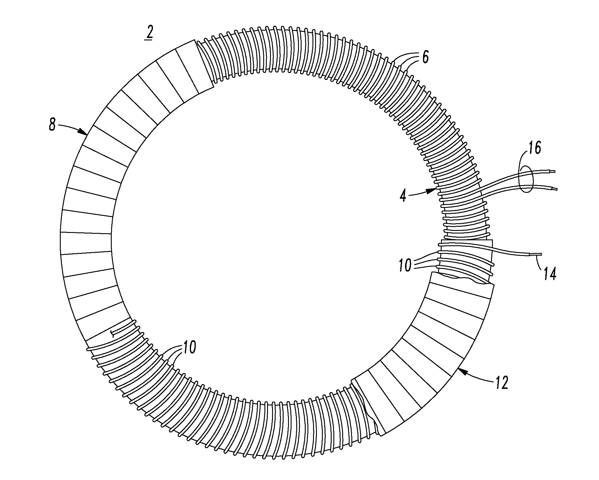
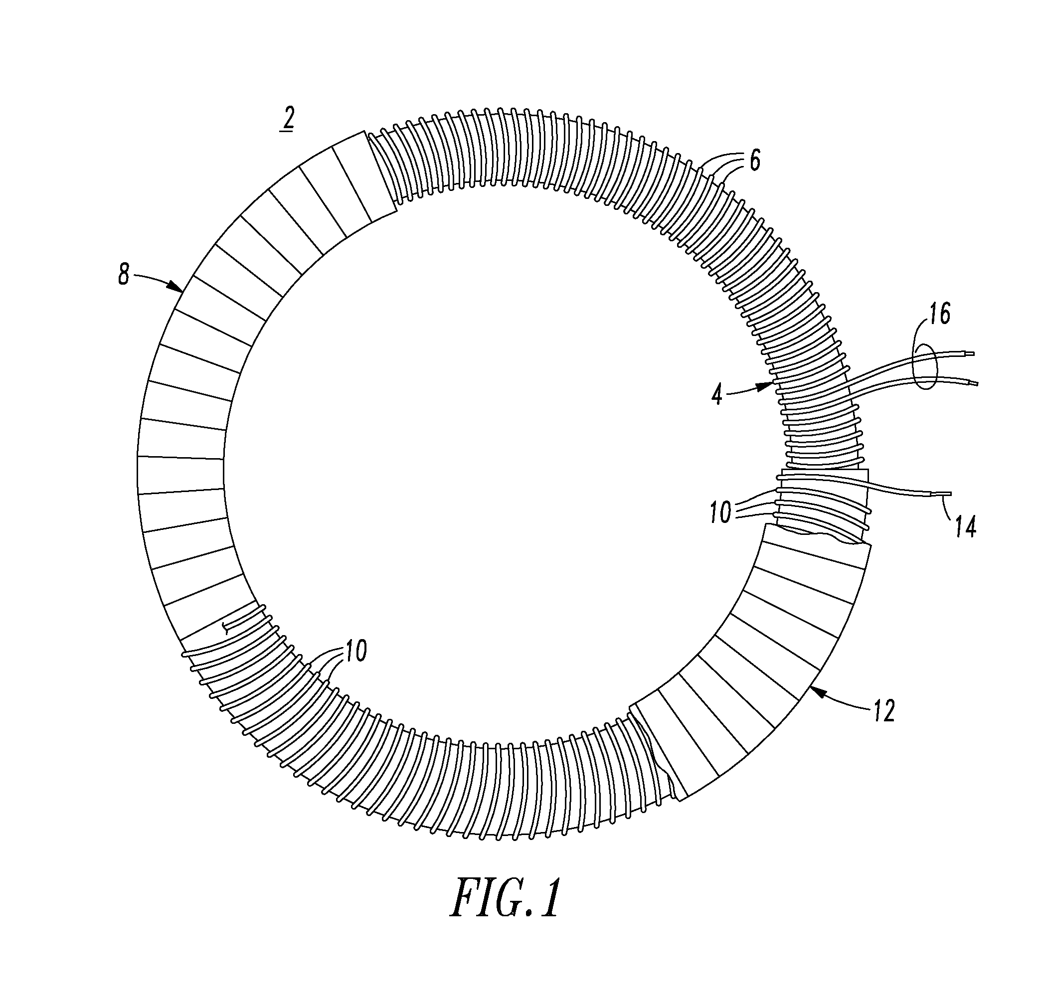
[0048]The conductive winding 10 can be a winding of a suitably fine insulated conductor (e.g., without limitation, an insulated copper wire; a relatively tightly wound magnet wire) wound on top of the Rogowski coil winding 6 to isolate the Rogowski coil winding 6 from electrostatic interference. The conductive winding 10, thus, provides an isolation coil. Preferably, the conductive winding 10 is wound “shoulder-to-shoulder” on the Rogowski coil winding 6 and is grounded at one end or lead 14 of the conductive winding 10 to provide isolation. The conductive winding 10 is electrically insulated from the Rogowski coil winding 6 by the insulator 8 (or, for example and without limitation, by another suitable insulator; by insulation of an insulated conductive winding; by insulation of the Rogowski coil winding). This provides a simple, yet very effective, solution to the problem of effectively and efficiently providing isolation for the Rogowski coil winding 6 to eliminate electrostatic ...

example 2

[0049]The example conductive winding 10 can be a helical coil of a conductor.

example 3

[0050]When grounded, the conductive winding 10 is structured to provide isolation to eliminate medium voltage electrostatic interference for the Rogowski coil winding 6 of the Rogowski coil 2.


PUM


Abstract

A Rogowski coil includes a core, a Rogowski coil winding disposed on the core, an insulator disposed on the Rogowski coil winding disposed on the core, and a conductive winding disposed on the insulator disposed on the Rogowski coil winding disposed on the core. The conductive winding includes an electrical connection structured to be grounded. When the conductive winding is grounded, the grounded conductive winding provides electrostatic shielding for the Rogowski coil winding of the Rogowski coil.

Description

BACKGROUND[0001]1. Field[0002]The disclosed concept pertains generally to medium voltage electrical apparatus and, more particularly, to such medium voltage electrical apparatus including a number of Rogowski coils. The disclosed concept also pertains to Rogowski coils. The disclosed concept further pertains to methods of providing electrostatic shielding for Rogowski coils.[0003]2. Background Information[0004]A Rogowski coil is an electrical device for measuring alternating current (AC) or high speed current pulses. The Rogowski coil includes, for example, a helical coil of wire, which is wound around a nonmetallic core.[0005]Another type of Rogowski coil includes first and second helical coils of wire (loops) electrically connected in series with each other. The first loop is wound with a substantially constant winding density in a first direction around a core that has a substantially constant cross section. The second loop is wound with a substantially constant winding density i...

Claims


Application Information

Patent Timeline
IPC IPC(8): G01R1/20H01F27/36
CPCG01R15/181H01F38/30H01F27/289
Inventor FARR, LAWRENCE B.
Owner EATON CORP
Why Eureka
Try Eureka