Portable electronic device

a portable electronic device and electronic technology, applied in static indicating devices, instruments, mechanical pattern conversion, etc., can solve the problems of increasing the size and weight of the portable electronic devi

Inactive Publication Date: 2011-02-24
CHI MEI COMM SYST INC
View PDF7 Cites 8 Cited by
  • Summary
  • Abstract
  • Description
  • Claims
  • Application Information

AI Technical Summary

Problems solved by technology

However, even though the magnetic devices may be small they still increase the size and weight of the portable electronic device.

Method used


Image

  • Portable electronic device
  • Portable electronic device
  • Portable electronic device

Examples


Embodiment Construction

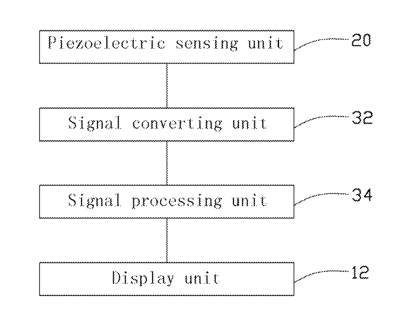
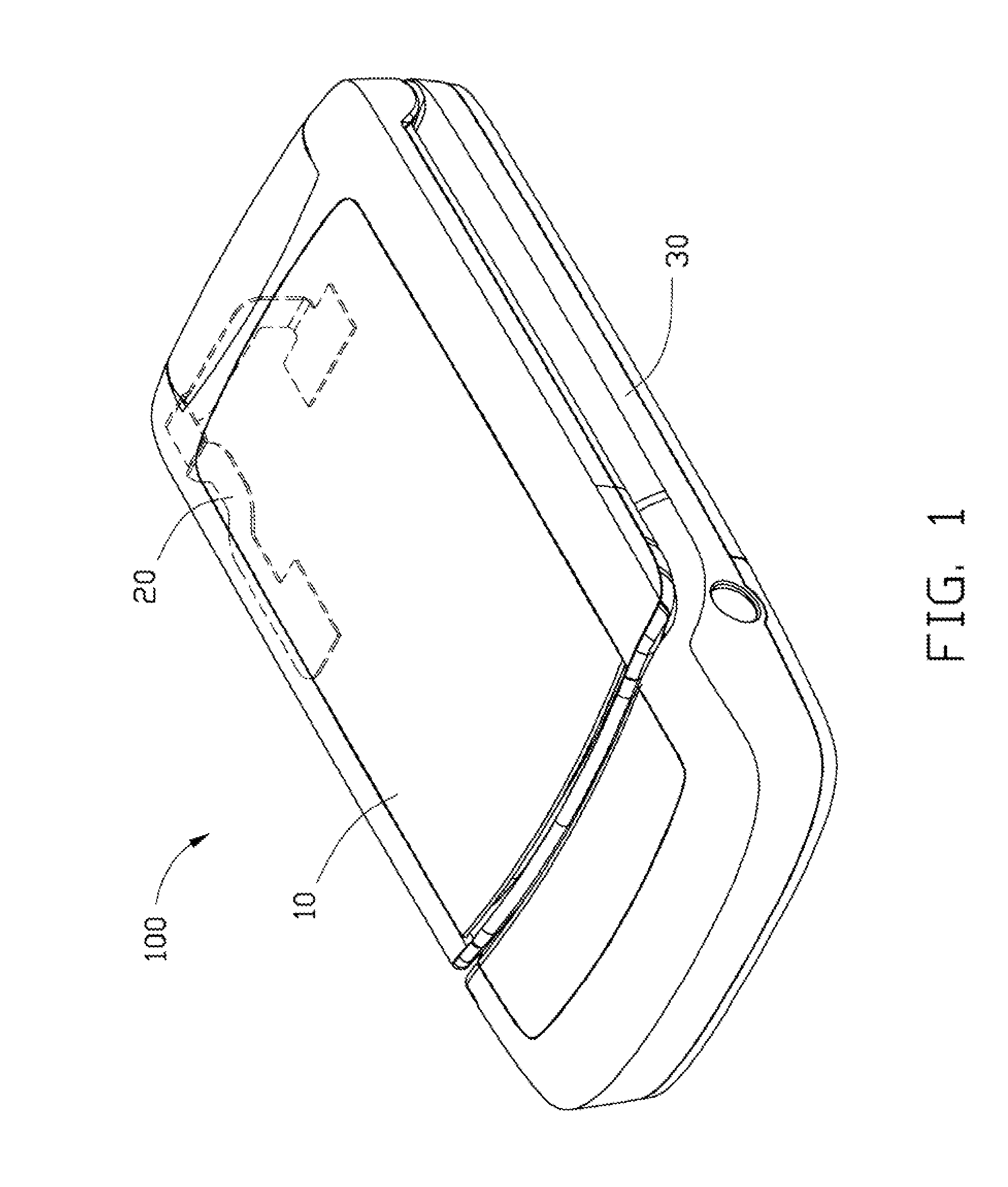
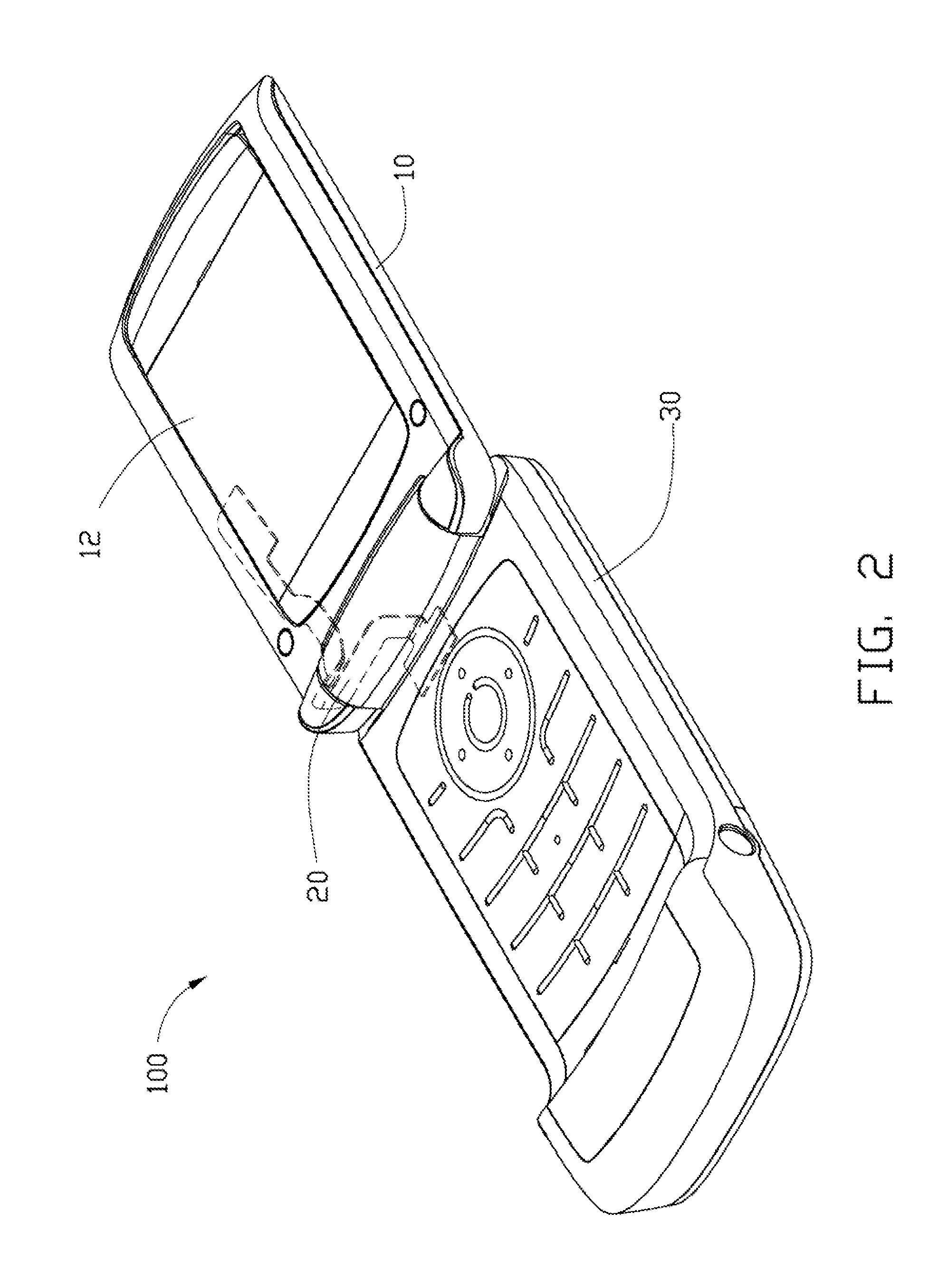
[0013]FIGS. 1-2 show an exemplary embodiment of a portable electronic device 100, which may be a PDA, a mobile phone, etc. The portable electronic device 100 may have a sliding structure or a flipping structure, a mobile phone with a flipping structure is used here as an exemplary application.

[0014]The portable electronic device 100 includes a cover 10, a piezoelectric sensing unit 20, and a main body 30. The cover 10 can be rotatably / movably connected to the main body 30. In this embodiment, the open position of the cover 10 is defined as a first position, and the closed position of the cover 10 is defined as a second position.

[0015]The portable device 100 further includes a display unit 12 centrally located in the cover 10, which can be integrated with an existing liquid crystal display module (LCM) of the mobile phone. The display unit 12 displays various information and operation instructions corresponding to different modes. When the cover 10 is flipped relative to the main bod...


PUM


Abstract

An exemplary portable electronic device includes a main body, a cover movably connected with the main body, a piezoelectric sensing unit, and a signal processing unit. The piezoelectric sensing unit is partially positioned on the main body and the cover. The piezoelectric sensing unit generates elastic deformation due to the relative displacement of the cover and the main body to generate a corresponding command signal. The signal processing unit is electrically connected to the piezoelectric sensing unit, and capable of actuating different modes of the portable electronic device according to the command signal.

Description

BACKGROUND[0001]1. Technical field[0002]The disclosure generally relates to portable electronic devices, more particularly, to a portable electronic device with flipping structure.[0003]2. Description of the Related Art[0004]Nowadays, flipping structures are widely used in mobile phones, personal digital assistants (PDAs) and other portable electronic devices. A flip-type electronic device generally has a main body and a flip cover. When the flip cover is rotated or flipped relative to the main body to a different position, the portable electronic device then can be switched to corresponding modes.[0005]Generally, most portable electronic devices switch to different modes previously associated with the movements of the flip cover by magnetic induction. A magnetic sensing device and a corresponding magnetic device are respectively disposed in the main body and the flip cover. When the flip cover rotates or flips relative to the main body to a different position, the magnetic sensing ...

Claims


Application Information

Patent Timeline
Patent Type & Authority Applications(United States)
IPC IPC(8): G06F3/01H04M1/72454
CPCG06F1/1677
Inventor PUN, CHING-CHIN
Owner CHI MEI COMM SYST INC
Why Eureka
Try Eureka