Computer input device

Inactive Publication Date: 2011-02-24
UNIV OF TEESSIDE
View PDF7 Cites 13 Cited by
  • Summary
  • Abstract
  • Description
  • Claims
  • Application Information

AI Technical Summary

Benefits of technology

[0033]One reference indicium may be arranged to be of a larger area another reference indicium whereby occlusion of an image of the one reference indicia by the other reference indicium may be substantially avoided.
[0042]The image capture device may be provided with a polarising element arranged to reduce an amount of light incident on a detector of the image capture device.
[0045]A size of an area of the image captured by the apparatus corresponding to one or more of the reference indicia may be expanded relative to a corresponding area of a portion of an image of the reference indicia that would be obtained under in-focus conditions whereby a position of a centroid of each of the one or more reference indicia in the image may be determined with increased precision.
[0055]Preferably the apparatus is configured to form an image of the reference indicia wherein an area of the image occupied by at least one of the indicia is expanded relative to a corresponding area of an image of the indicia under in-focus conditions whereby a position of a centroid of the area of the image occupied by each of the indicia may be determined with increased precision.
[0064]Preferably the apparatus is further configured such that a size of an area of the image captured by the apparatus corresponding to one or more of the reference indicia is expanded relative to a corresponding area of a portion of an image of the reference indicia that would be obtained under in-focus conditions whereby a position of the centroid of each of the one or more reference indicia in the image may be determined with increased precision.

Problems solved by technology

None of the documents discloses a system allowing detection of movement of an input device in three mutually orthogonal directions.
Such systems are limited in the range of angles of the marker with respect to the camera over which orientation of the object can be determined.
Known systems also have a limited range of operation in terms of the distance from the camera to the marker.

Method used


Image

  • Computer input device
  • Computer input device
  • Computer input device

Examples


example 1

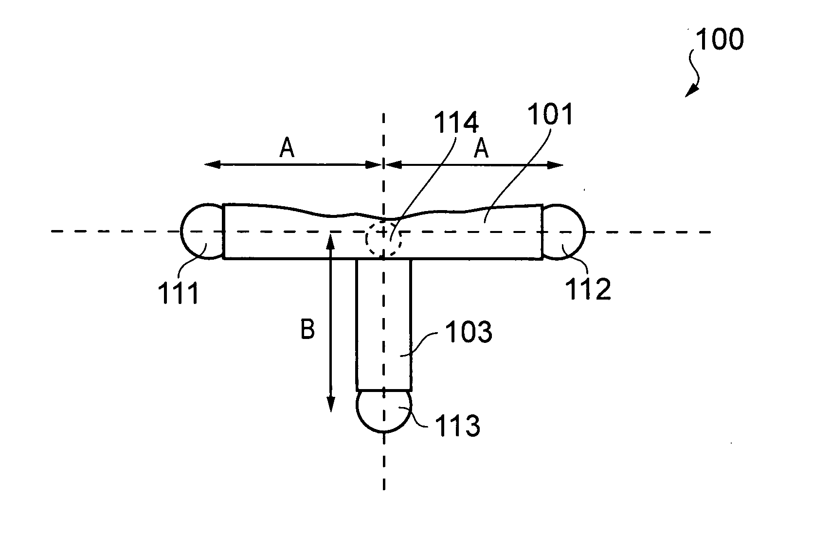
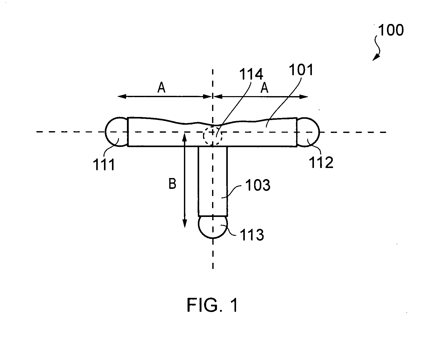
[0139]FIG. 13 shows a graph of movement of a pointing device 100 relative to an image capture device 130 using apparatus of an embodiment of the invention. The image capture device 130 was a 640×480 pixel webcam device of the type used in typical internet-based communication applications.

[0140]Three separate traces are shown in the graph. Trace X corresponds to a position of the virtual point 114 with respect to the origin O along the x-axis. Trace Y corresponds to a position of the virtual point 114 with respect to the origin O along the y-axis and trace Z corresponds to a position of the virtual point 114 with respect to the origin O along the z-axis.

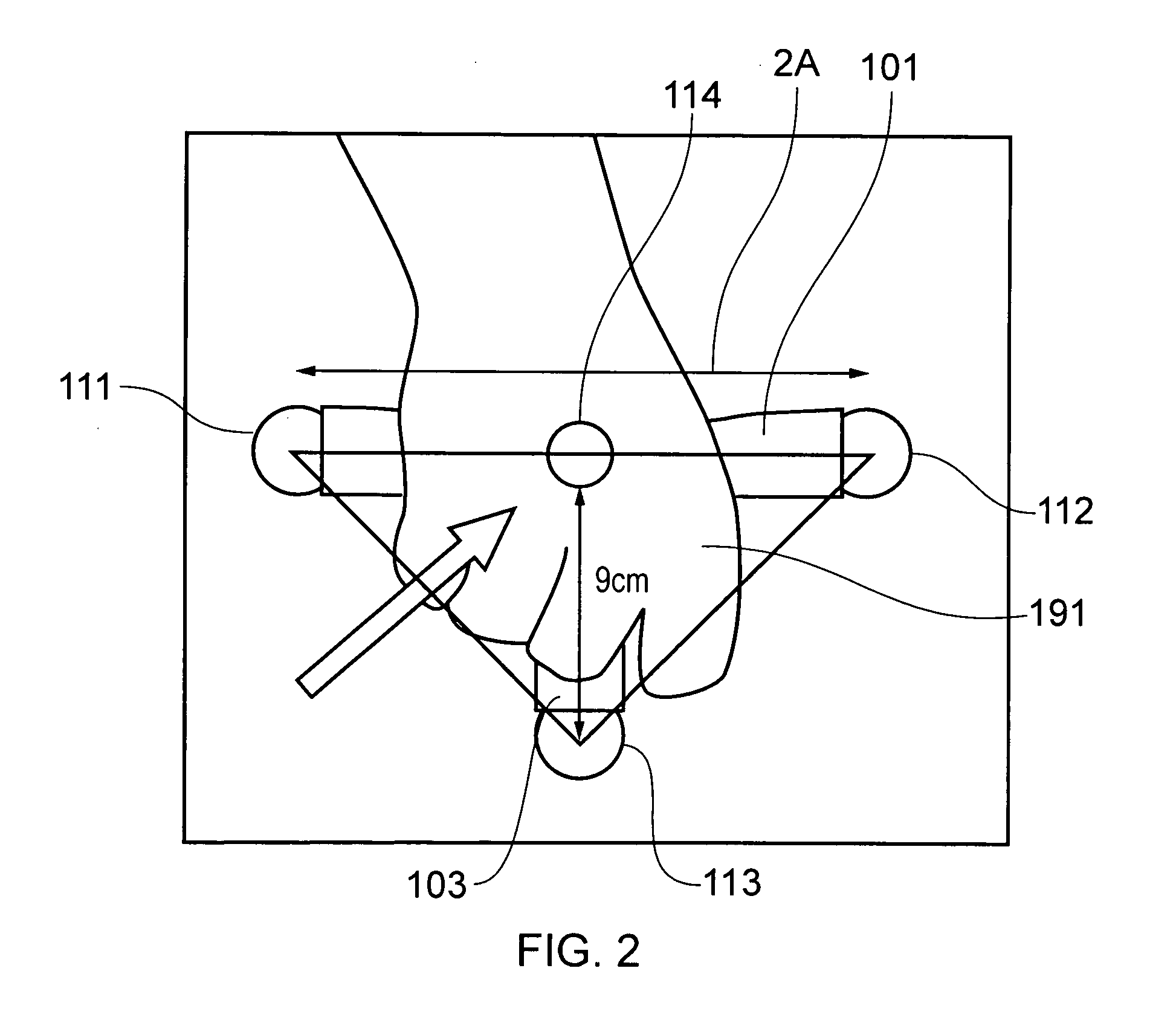
[0141]With respect to a user 190 positioned as shown in FIG. 13, the form of trace X in the graph of FIG. 13 therefore corresponds to side-to-side movement of pointing device 100 (i.e. movement along the x-axis only). Trace Y corresponds to upwards-downwards movement of the pointing device 100 (i.e. movement along the y-axis only) whi...


PUM


Abstract

Computer input apparatus comprising: an image capture device; and a marker member comprising at least two reference indicia, at least a first reference indicium being arranged to emit or reflect light having a first spectral characteristic, and at least a second reference indicium being arranged to emit or reflect light having a second spectral characteristic different from the first spectral characteristic, the image capture device being arranged to distinguish light of said first spectral characteristic from light of said second spectral characteristic thereby to distinguish the at least a first reference indicium from the at least a second reference indicium, the apparatus being configured to capture an image of the at least two reference indicia and to determine by means of said image a position and orientation of the marker member with respect to a reference frame.

Description

FIELD OF THE INVENTION[0001]The present invention relates to an input device for a computer. In particular but not exclusively the invention relates to an input device to be worn by or held by a user.BACKGROUND[0002]A variety of computer input devices are known arranged whereby manual manipulation of the device allows one or more commands to be transmitted to a computer. Examples include a mouse, touch screen, touch pad, joystick and other controllers.[0003]US2007 / 0049374 (NINTENDO) discloses a game system having a pair of controllers arranged to be held one in a left hand and one in a right hand of a user. One controller has an acceleration sensor and an image pickup section that includes a camera. A pair of infra-red light emitting diodes (LEDs) are provided on a monitor of the game system. The system is arranged to process an image acquired by the image pickup section and to detect a position of the LEDs within the image. Movement of the controller can result in a change of posit...

Claims


Application Information

Patent Timeline
IPC IPC(8): G09G5/00
CPCG06F3/038G06F3/0325
Inventor SPEARS, IAINBRUNTON, TIMOTHYTANG, WEN
Owner UNIV OF TEESSIDE
Why Eureka
Try Eureka