
Base station, mobile station, and mapping method of subcarriers

a subcarrier and mobile station technology, applied in the direction of transmission path division, wireless commuication services, signalling characterisation, etc., can solve the problems of low efficiency, inability to cope with channel environment changes, loss of control signals of high importance, etc., and achieve the effect of effectively using subcarriers

Inactive Publication Date: 2011-02-24
LENOVO INNOVATIONS LTD HONG KONG
View PDF11 Cites 2 Cited by
  • Summary
  • Abstract
  • Description
  • Claims
  • Application Information

AI Technical Summary

Benefits of technology

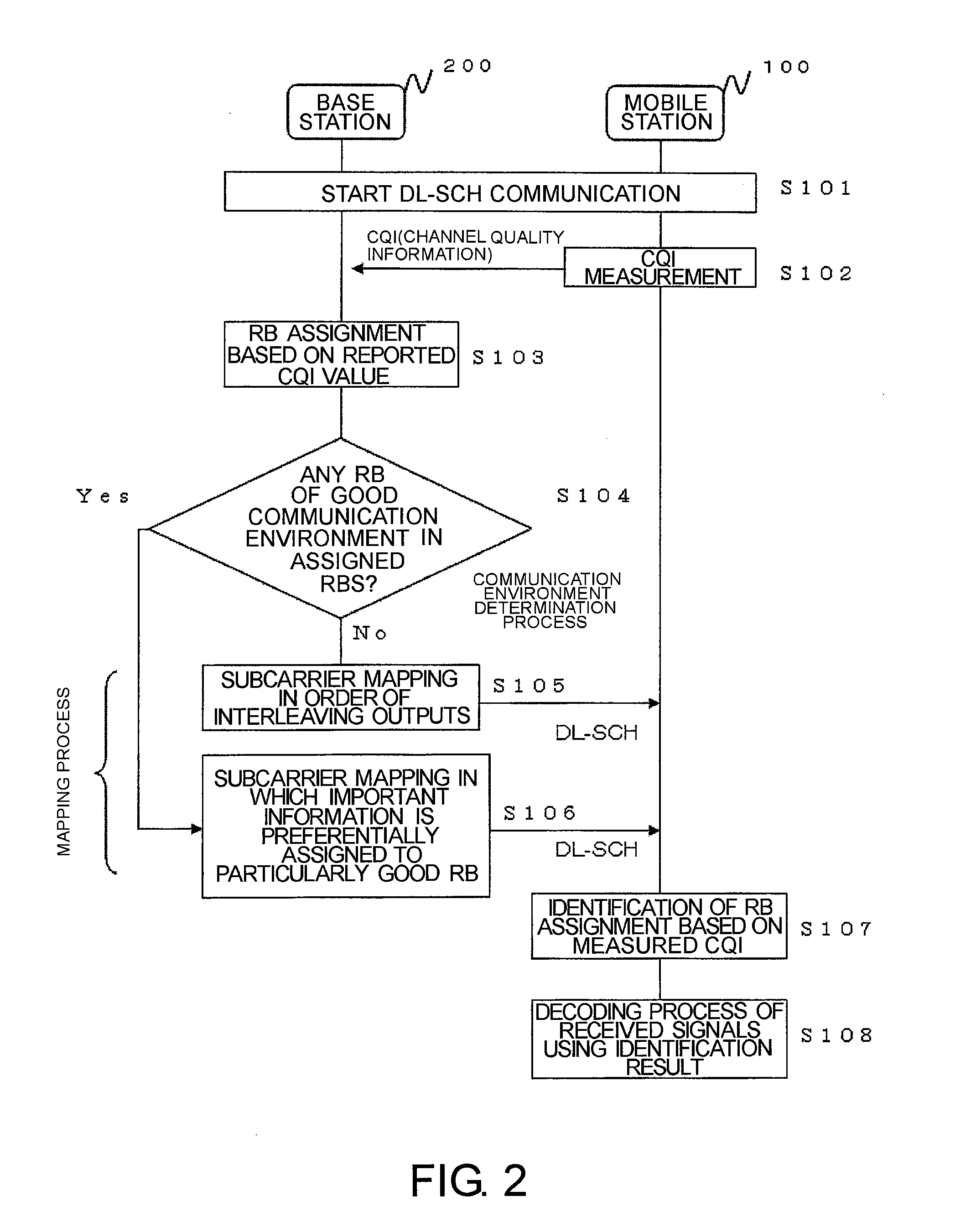
The present invention provides a mapping method for subcarriers that can adapt to changes in the communication environment and use subcarriers effectively with channel quality information. The base station identifies the communication environment and maps transmission information selectively to a specified subcarrier based on the identified condition. This helps to ensure high-quality communication even in challenging environments.

Problems solved by technology

However, the technique disclosed in Patent Document 1 cannot cope with changes of channel environments due to fading.
In other words, if a communication environment of subcarriers changes, there is a chance that a control signal of high importance is lost.
Furthermore, although the technique disclosed in Patent Document 2 can reduce the influence of frequency variation (frequency fading) of subcarriers with use of a frequency hopping pattern, it cannot cope with frequencies other than predetermined frequency variations (hopping pattern) or changes of channel environments due to fading resulting from locations, time, or the like.
In other words, if a communication environment of subcarriers changes due to frequency variations or positional variations (movements), there is a chance that a control signal of high importance is lost.

Method used


Image

  • Base station, mobile station, and mapping method of subcarriers
  • Base station, mobile station, and mapping method of subcarriers
  • Base station, mobile station, and mapping method of subcarriers

Examples


Embodiment Construction

[0025]An embodiment of the present invention will be described based upon FIGS. 1 to 3.

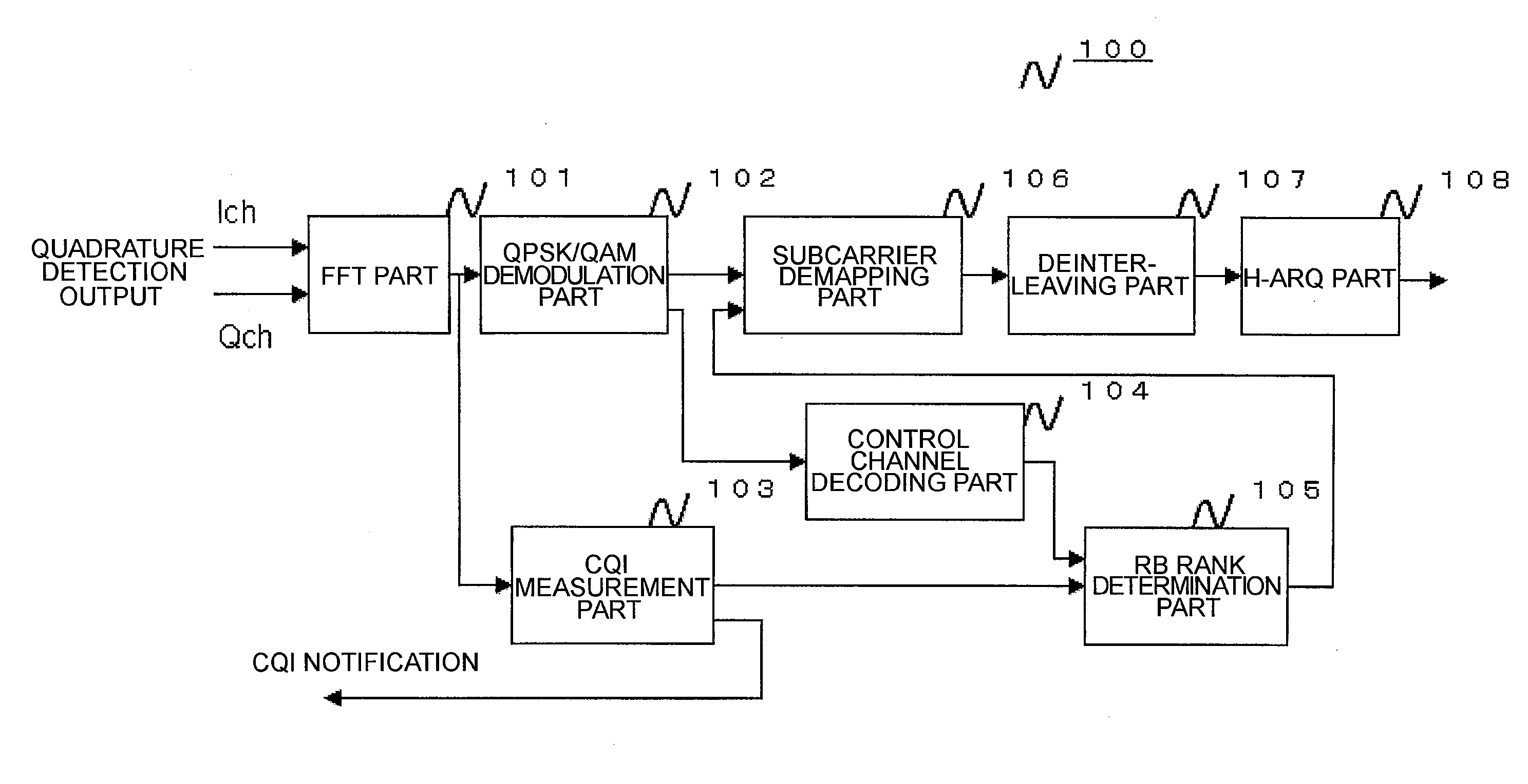
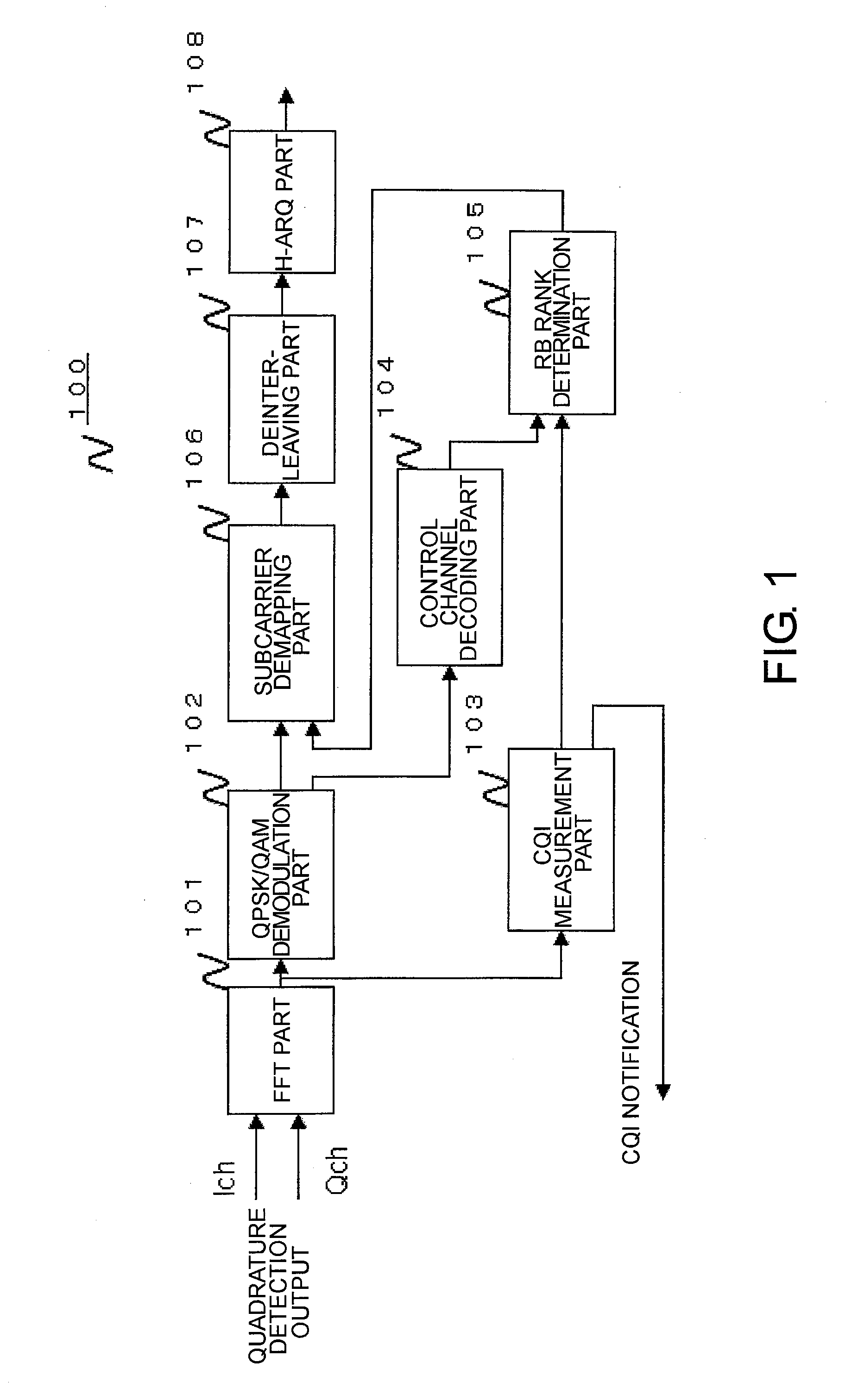
[0026]FIG. 1 is a block diagram showing part of a mobile station 100 according to the embodiment. FIG. 1 is a portion of a general block diagram showing the mobile station and shows features of the present invention.

[0027]A FFT (Fast Fourier Transform) part 101 is configured to receive Ich and Qch signals subjected to quadrature detection and transmit subcarrier signals to a QPSK / QAM demodulation part 102 and a CQI measurement part 103.

[0028]The QPSK / QAM demodulation part 102 is configured to receive the subcarrier signals, demodulate the subcarrier signals into symbols, and transmit the demodulated symbols to a subcarrier demapping part 106 and a control channel decoding part 104.

[0029]The CQI measurement part 103 is configured to receive the subcarrier signals, measure CQIs, transmit the measured CQIs to a base station, and concurrently transmit the CQIs to a RB (Resource Block) rank determinati...


PUM


Abstract

In order to cope with changes of communication environments of subcarriers and effectively use the subcarrier with channel quality information in a wireless communication system, a base station identifies a condition of a communication environment between the base station and a mobile station based upon channel quality information transmitted from the mobile station and maps transmission information on control of communication selectively to a specified subcarrier used for transmission based upon the identified condition of the communication environment.

Description

TECHNICAL FIELD[0001]The present invention relates to a wireless communication system and mapping of carriers used in wireless communication.BACKGROUND ART[0002]The communication method being developed as an LTE (Long Term Evolution) by 3GPP (3rd Generation Partnership Project) aims at a high throughput of at least 100 Mbps. Additionally, future traffic is expected to increase along with today's remarkable development of diversification in various communication services. In order to cope with such future traffic, communication methods having a high throughput have also been demanded. For this purpose, many inventions have been made in order to improve a throughput of the entire communication system.[0003]The wireless communication technology has continuously been evolved with the aforementioned inventions and the like. This evolution can be a considered as an outcome of the research and development in various fields, including selection of a frequency band of radio waves, transmissi...

Claims


Application Information

Patent Timeline
Patent Type & Authority Applications(United States)
IPC IPC(8): H04W72/04
CPCH04B1/59H04L2001/0098H04L5/0046H04L1/0017H04L1/0026H04L5/0007
Inventor TAMURA, KOICHI
Owner LENOVO INNOVATIONS LTD HONG KONG
Learn More