Real Time Urine Monitoring System

a real-time, urine-monitoring technology, applied in the field of medical instruments and systems, can solve the problems of requiring arduous physical labor to use, the closed urine collection system currently in wide use is not automated, and the current system is error-pron

Inactive Publication Date: 2011-02-24
GREENWALD TECH
View PDF15 Cites 54 Cited by
  • Summary
  • Abstract
  • Description
  • Claims
  • Application Information

AI Technical Summary

Problems solved by technology

The closed urine collection system currently in wide use is not automated and relies on a subjective interpretation of urine level relative to printed volumetric markings either on a rigid small volume collection tray or a larger volume collapsible collecting bag.
The current system is: error prone, requires arduous physical labor to use, demands repeated potential exposures to biohazordous materials, and is inefficient.
Erroneous urine output value recordings can arise from the antiquated design of the currently widely used closed catheter system leading to improper clinical responses.
These errors come most commonly in the form of subjective errors in interpreting urine volumetric markings, arithmetic errors, and neglected readings.
These errors in urine output interpretation mean an incorrect patient total body volume assessment causing clinicians to over or under resuscitate their patients which may cause serious complications including renal failure, cardiovascular collapse, or pulmonary edema to name only a few.
The current urine collection system requires the medical staff member to squat or bend down at the bedside to the low position where the gravity dependent collection bag is stored, which can become quite labor intensive when repeated multiple times throughout the day.
Thus as it now stands, the monitoring of urine output is both physically strenuous and may expose clinical staff to leaked biohazardous material due to frequent daily handling of the urine collecting receptacle and long tube.
If the clinical data lags behind the patient's course, decisions become delayed and patients can suffer dire consequences.
A system with even some nondisposable components meant for re-use puts patients and hospital staff at risk of contracting hospital acquired infection.
The system utilizes a two bag system with one bag collecting urine before passing through a drop generator, which means that this system is unable to handle medium to high urine flow in real time.
Also, this system contains expensive components and thus can not practically be entirely disposable, and it requires fixation in the upright position due to the overflow conduit connecting the upper and lower bags.
Both U.S. Pat. No. 5,891,051 by Han, et al. and U.S. Pat. No. 4,448,207 by Parrish describe automated urine monitoring systems utilizing ultrasound to measure the volume of urine accumulated in a rigid collecting chamber, which limits the resolution available.
The current cost of ultrasound technology would make disposal prohibitive, and the systems must remain in the fixed upright position for the ultrasound sensor to accurately measure the urine volume in the rigid collecting chamber.
Both of these are limited in accuracy at low urine flow.
In addition the rotometer of Nehrbass requires a minimum pressure-head to operate which is difficult to achieve at low flow, and for the rotometer system to work, the conduit tube where the rotometer is installed must be completely full with urine which does not occur with low flow.
This multi-valve system does not handle either high or low urine flow rates in real time.

Method used


Image

  • Real Time Urine Monitoring System
  • Real Time Urine Monitoring System
  • Real Time Urine Monitoring System

Examples


first embodiment

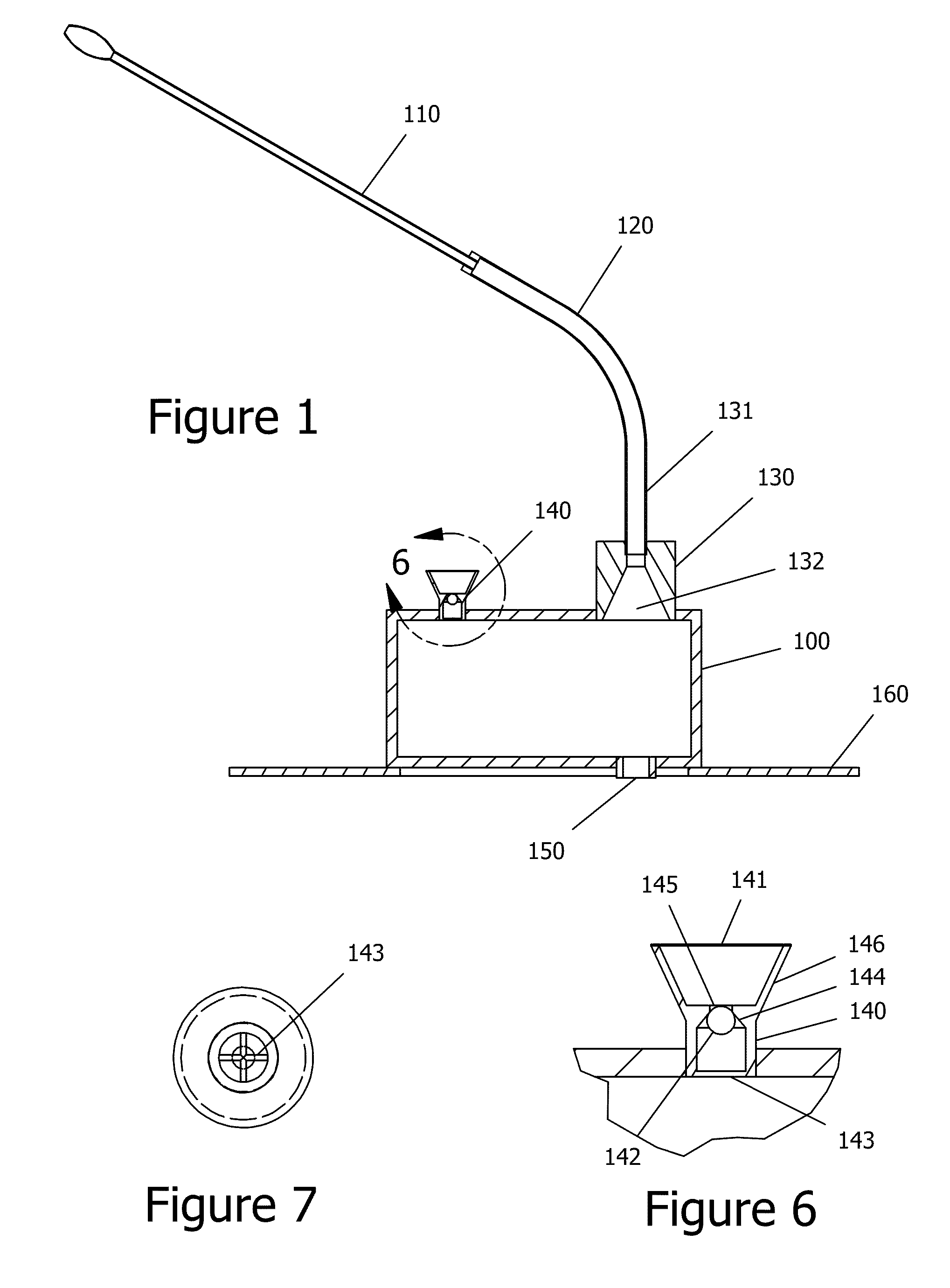
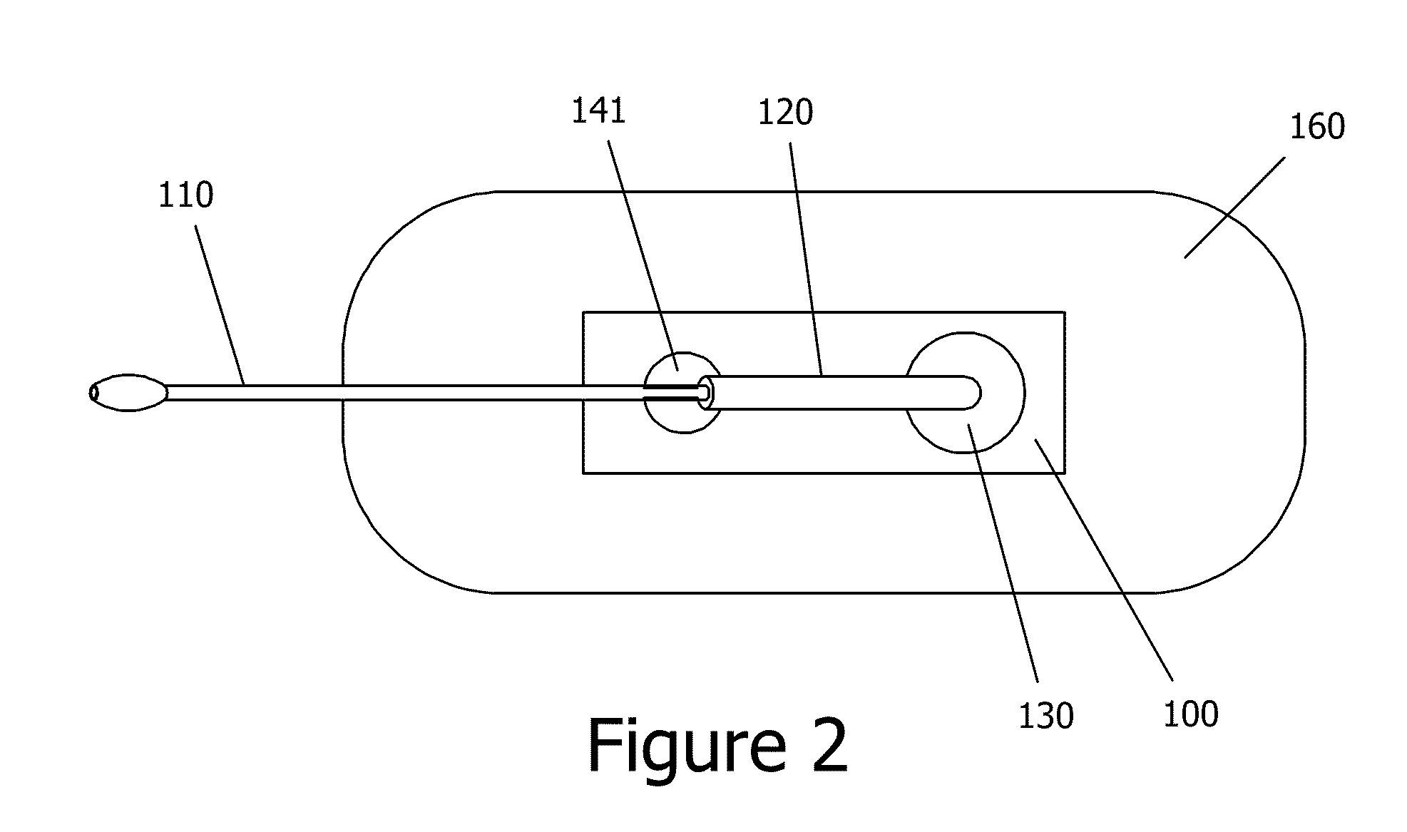
In the urine output monitoring system, as shown in FIG. 3, the exit port 150 of the pressure chamber 100 will be fitted with a rigid short tube 220 and a second opening at the bottom of the pressure chamber 100 will be fitted with a small pressure sensor 240. A nozzle 210 is fitted into the top part of the short rigid tube 220 and drains urine from the pressure-chamber 100 directly into the short rigid tube 220. Typically the length of the short rigid tube 220 will be a few inches long, with an inner diameter of ⅜ of an inch and an outer diameter of less than one inch.

A low flow sensor 230 is mounted on both sides of the short rigid tube 220 adjacent to the lower surface of the pressure chamber 100. This sensor is preferably an RF energy type sensor as described in U.S. Pat. No. 7,482,818 or in co-pending U.S. patent application Ser. No. 12 / 334,980, which are incorporated herein by reference. It will be understood, however, that other sensors might be used within the teachings of th...

second embodiment

In a second embodiment, as is shown in FIG. 4, the exit port 150 at the bottom of the pressure chamber 100 is fitted with a small opening that will drain directly into a conduit 400 coupled to an ultrasonic flow sensor 420. The conduit 400 consists of a capillary tube 411, 421 and 412 shaped like the letter “W” with the last arm 412 of the “W” shape attached to a larger diameter rigid tube 430 that will break capillary flow and drain into the collecting bag 260. A conduit with only two capillary tubes shaped like a “V”, or three capillary tubes shaped like a rotated S, can also be used within the teachings of the invention, and other arrangements are possible.

In this embodiment, conduit 400 has five arms all together: four arms shaped in a “W” with capillary flow, and a fifth arm 430 with regular flow. Preferably, the ultrasonic flow meter 420 will be located on the third arm 421 of the “W” shape, although other placements on other arms of the “W” are possible.

Typically the height o...

third embodiment

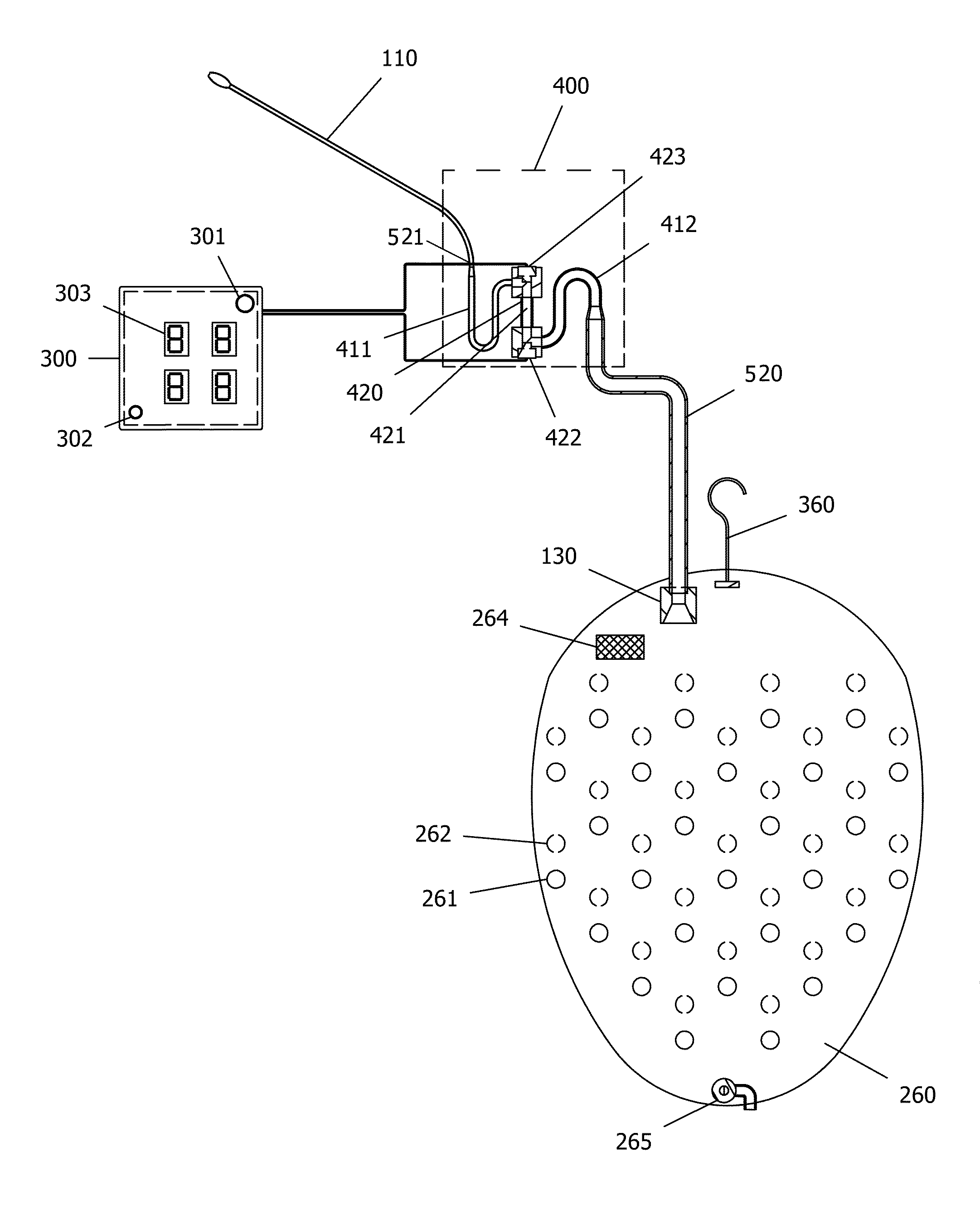
In a third embodiment, the ‘W’ shaped conduit 400 together with the ultrasonic flow sensor 420 directly between a catheter connector 521 into which is plugged a Foley catheter 110 and long tube 520, without the use of a pressure chamber, as can be seen in FIG. 5. The Foley catheter 110 itself is a capillary tube due to its narrow diameter and only passes urine and no air into the ‘W’ shaped conduit 400. As was explained above the W shaped conduit will maintain liquid in the ultrasonic flow meter channel at all times which is essential for obtaining accurate measurements. Also the W conduit allows optimizing the ultrasonic flow meter channel 421 diameter and material to achieve the needed accuracy for the high flow and low flow.


PUM


Abstract

A disposable real-time closed catheter urine output monitoring system. The monitoring system of the invention can measure urine outputs at both high and low urine flow in real time, using a pressure chamber in the form of a hollow body having an input port for coupling to a tube connected to a catheter for collection of urine from a patient, an exit port coupled to a collection container and a vent port, such that air may flow through the vent, but urine is blocked by the vent. A sensor measures flow from the exit port of the pressure chamber into the collection container, and a pressure sensor may be included to measure pressure in the pressure chamber. The invention also provides a method of using the apparatus in a real-time monitoring system.

Description

BACKGROUND OF THE INVENTION1. Field of the InventionThe invention pertains to medical instrumentation systems. More specifically, the invention pertains to urine measuring systems.2. Description of Related ArtAccurate real time urine output recording is essential to patient management in both the acute and non-acute settings. The closed urine collection system currently in wide use is not automated and relies on a subjective interpretation of urine level relative to printed volumetric markings either on a rigid small volume collection tray or a larger volume collapsible collecting bag. The current system is: error prone, requires arduous physical labor to use, demands repeated potential exposures to biohazordous materials, and is inefficient.Erroneous urine output value recordings can arise from the antiquated design of the currently widely used closed catheter system leading to improper clinical responses. These errors come most commonly in the form of subjective errors in interpre...

Claims


Application Information

Patent Timeline
Patent Type & Authority Applications(United States)
IPC IPC(8): A61B5/20G01F1/00
CPCA61B5/208G01F1/662A61B10/007
Inventor GREENWALD, SHLOMOGREENWALD, ZIPORAGREENWALD, URI MOSHE
Owner GREENWALD TECH
Why Eureka
Try Eureka