Solar reflector

Inactive Publication Date: 2011-03-03
SOLEIR
View PDF10 Cites 11 Cited by
  • Summary
  • Abstract
  • Description
  • Claims
  • Application Information

AI Technical Summary

Benefits of technology

[0017]Preferably the solar absorber includes a solar absorber pipe adapted for a fluid to flow. More preferably the fluid is a liquid adapted to absorb the heat reflected and concentrated by the reflector panel. Even more preferably the heat absorbed by the liquid is used to generate electricity:
[0018]Preferably the solar

Problems solved by technology

As the fuel (in the form of sunlight) for such systems is renewable and essentially free, a challenge for making such system

Method used


Image

  • Solar reflector
  • Solar reflector
  • Solar reflector

Examples


Embodiment Construction

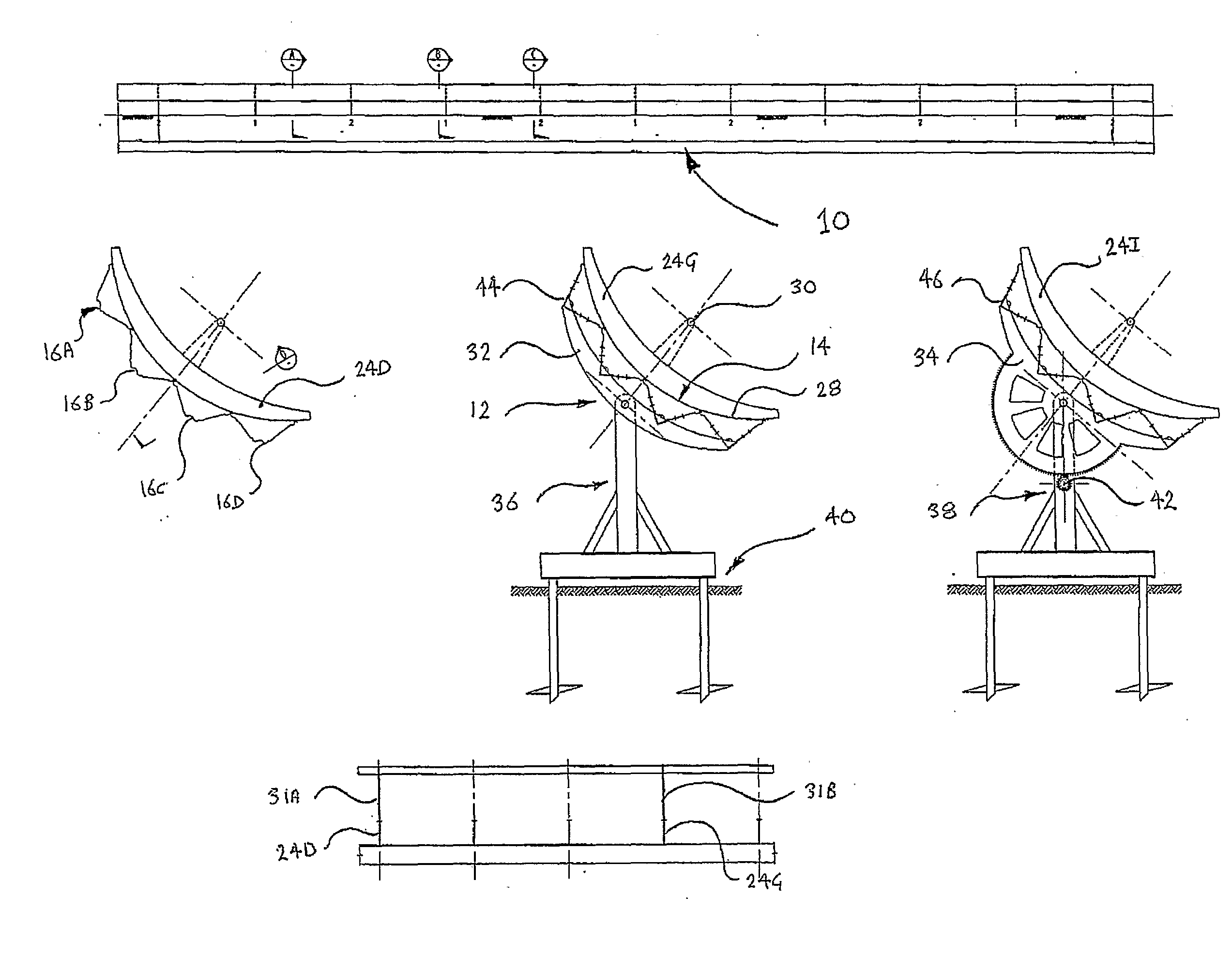
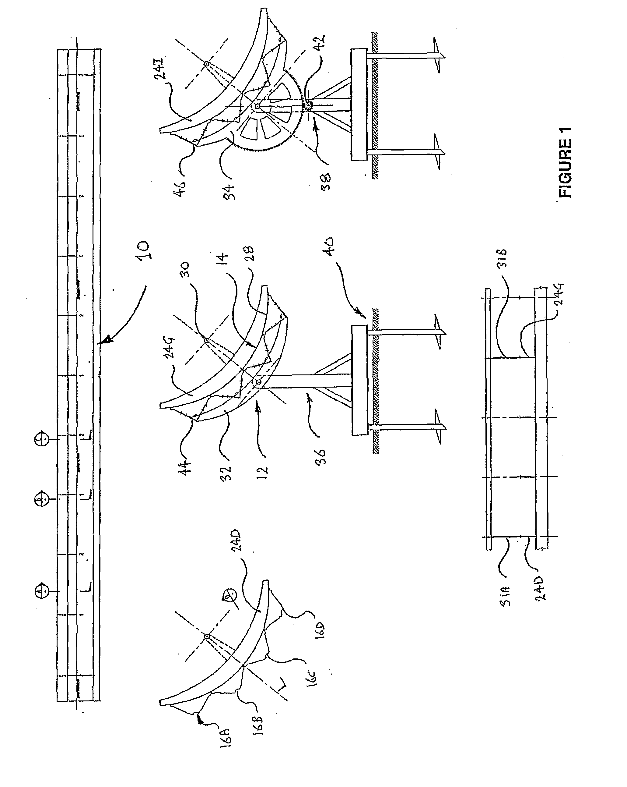
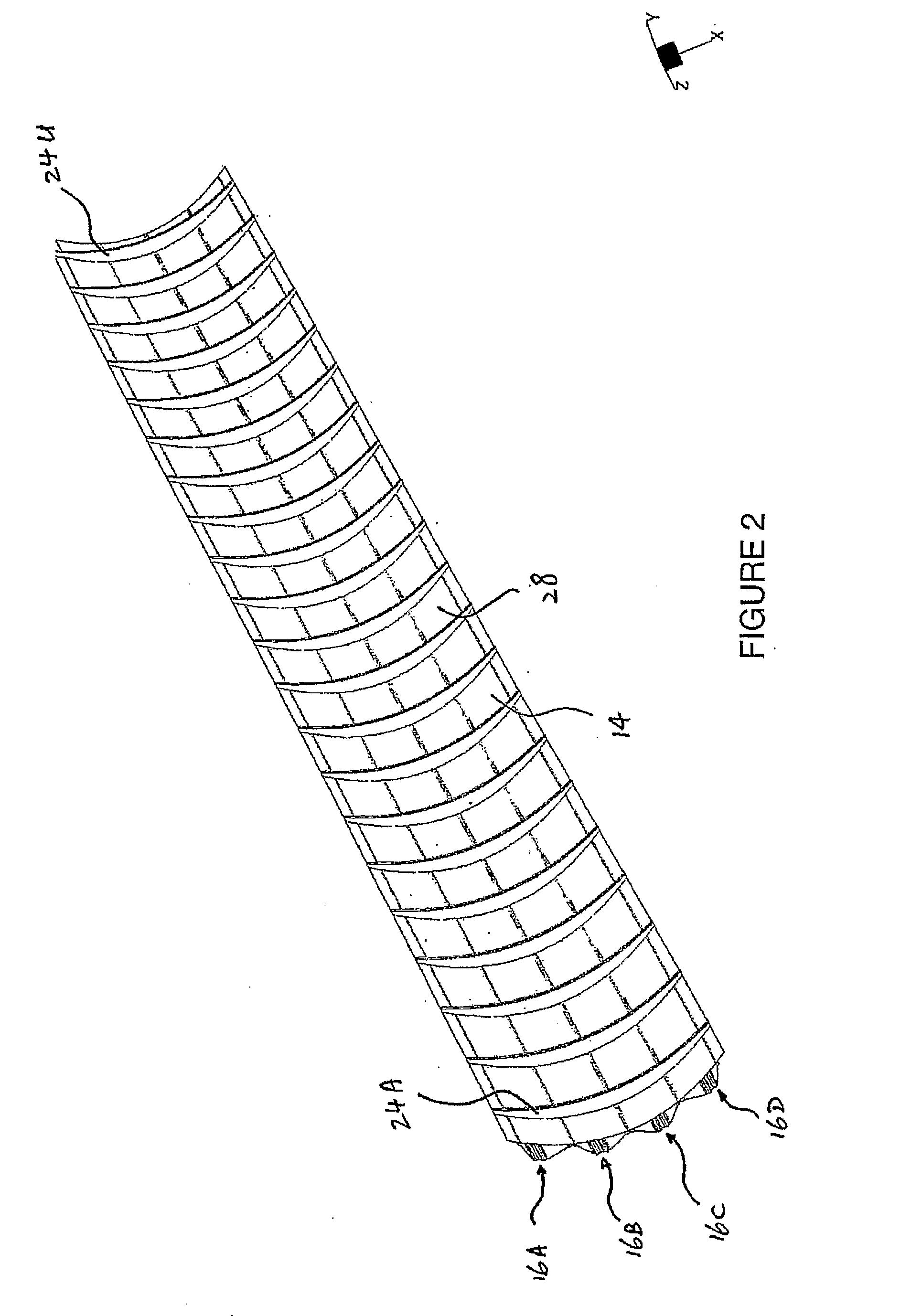
[0029]As best shown in FIG. 1 there is solar reflector assembly 10 comprising a corrugated support structure 12 and a reflector panel 14. The support structure 12 includes a plurality of support panels such as 16A to 16D each having a generally V-shaped cross-section. The support panels 16A to 16D are interlocked and connected to a lower facing surface of the reflector panel 14 which is designed to reflect and concentrate light energy.

[0030]As best shown in FIG. 3, in this embodiment the V-shaped support panels such as 16A are each formed by a pair of inclined side flanges 18A and 20A interconnected by an intermediate web 22A. This cross sectional configuration defines an elongate groove or trough 23 bordered by opposing ridges such as 25. These elongate panels are otherwise constructed in accordance with Australian patent no. 726159 by Wade Hylton Blazley and its foreign counterparts. The disclosure of this Australian patent and its foreign counterparts is to be included herein by ...


PUM

PropertyMeasurementUnit
Flow rateaaaaaaaaaa
Energyaaaaaaaaaa
Heataaaaaaaaaa

Abstract

In one embodiment of the invention, there is provided a solar reflector assembly comprising a corrugated support structure and a reflector panel. The support structure includes a plurality of support panels each having a generally U or V-shaped cross-section. The support panels are interlocked and connected to a lower facing surface of the reflector panel which is designed to reflect and concentrate light energy. The solar reflector assembly of this embodiment may further comprises a solar absorber in the form of a pipe and/or including photovoltaic strip for collecting the concentrated the light energy.

Description

FIELD OF THE INVENTION[0001]The present invention relates broadly to a method of constructing a solar reflector assembly together with the solar reflector assembly itself.BACKGROUND OF THE INVENTION[0002]There exists in Australia and elsewhere several solar thermal array systems which are designed to convert solar energy into electricity via the heating of water or other liquids to drive electricity generating turbines. Such systems typically involve an elaborate structure which supports parabolic solar reflectors where the structure can pivot with the position of the sun so as to constantly concentrate reflected sunlight onto overhead pipes through which the liquid is heated and delivered to a heat engine or heat exchanger. As the fuel (in the form of sunlight) for such systems is renewable and essentially free, a challenge for making such systems economically viable, involves the design and construction of low cost pivoting structures to support the solar reflectors.SUMMARY OF THE...

Claims


Application Information

Patent Timeline
IPC IPC(8): F24J2/12F24J2/52F24J2/02H01L31/052H01L31/18F24S10/70F24S20/30F24S23/71F24S90/00
CPCF24J2/14F24J2/541Y10T29/49355Y02E10/45Y02E10/47Y02B10/20F24S23/74F24S30/425Y02E10/40
Inventor FOONG, EDWINGILLESPIE, ROHAN
Owner SOLEIR
Why Eureka
Try Eureka