
Solar dryer with enhanced efficiency of drying

Inactive Publication Date: 2014-07-03
COUNCIL OF SCI & IND RES
View PDF10 Cites 9 Cited by
  • Summary
  • Abstract
  • Description
  • Claims
  • Application Information

AI Technical Summary

Benefits of technology

The present invention is a solar dryer that improves drying efficiency. It achieves this by using solar reflectors to increase the amount of sunlight that collects on the collector. This makes the air temperature hotter, which in turn makes the drying process faster. The dryer also has a foldable reflector assembly, making it can be operated in direct or indirect mode.

Problems solved by technology

Clearly, the operation would entail use of large amounts of dessicant especially when food products contain high levels of moisture.
The main drawback of the system is that the temperature reached by this type of arrangement is fairly low (60° C.) and is not appropriate to dry all food products.
Constant monitoring of the dryer position to adjust the tracking mechanism is the main drawback of the system.
Although the dryer was not a solar operated one, the authors concluded that recirculating exhaust air from start of the drying process could adversely affect the drying air quality and could result in significant increase in drying time.

Method used


Image

  • Solar dryer with enhanced efficiency of drying
  • Solar dryer with enhanced efficiency of drying
  • Solar dryer with enhanced efficiency of drying

Examples


example 1

[0094]The solar dryer of FIGS. 1-7 was taken without any reflectors in one case and with reflectors on the collector side in another case. For measurements made on two typical days in the month of March under almost similar ambient conditions, the drying air temperatures recorded from 11 am to 4.30 pm are tabulated in Table 1.

TABLE 1Drying air temperature profile inside theunit with and without use of reflectorsInsolationWith ReflectorsWithout ReflectorsTime (h)(W m−2)Tco (° C.)Tco (° C.)11:0079697.37611:3086998.881.412:00911101.184.612:3088199.689.313:00881100.886.813:3089310386.114:00917106.584.414:30834104.584.415:00754102.883.515:3068397.783.516:005889180.116:3047285.478.6

[0095]This example teaches us the enhancement in the temperature profile of drying air throughout the day with the use of reflectors on collector side.

example 2

[0096]The dc fans were operated directly using the 10 watt solar PV panel. The following table shows that the speed of the fan in r.p.m, measured by a tachometer depends on the variation of solar intensity for that particular day. Since the powering of the fan is by the solar PV panel, with increase in solar intensity, the power output from the panel increases and this enhances the speed of the fan. The data was collected for a condition when the reflectors on the dryer chamber were absent.

TABLE 2Variation of fan speed with solar intensity and calculatedmass flow rate of air inside the dryer.Time (h)Insolation (W m−2)Fan rpm11:30879307612:00950343412:30974358413:001188545213:30998462214:00831304214:30784294915:00689270815:30630270616:00404266716:303802585

[0097]This example teaches us that during peak insolation, the fan also runs with a very high rpm. This effect is advantageous for the drying process, as it helps to control the temperature inside the drying chamber, such that, at h...

example 3

[0098]The Experiment of Example 2 was repeated on two similar solar dryers. In one case the fan speed was fixed at 2700 rpm whereas in the other case the fan speed varied with solar insolation. The collector outlet temperature, Tco (° C.), is shown as a function of time of day for both cases in the table below.

Tco (° C.) of unitTco (° C.) of unit with fanSolarwith fan havinghaving variable speedinsolationfixed speedsynchronized withTime (h)(W m−2)(2700 RPM)insolation11:309418477.512:0092391.783.212:308589081.913:0087587.281.313:3090581.879.514:0090573.279.114:3077876.580.515:3065968.276.816:0055262.172.3

[0099]The above example teaches us that with a fixed speed fan, Tco varied from 62.1° C. to 90° C., whereas by using a fan connected directly to the PV panel it was better controlled and lay in the range of 72.3° C. to 83.2° C.


PUM


Abstract

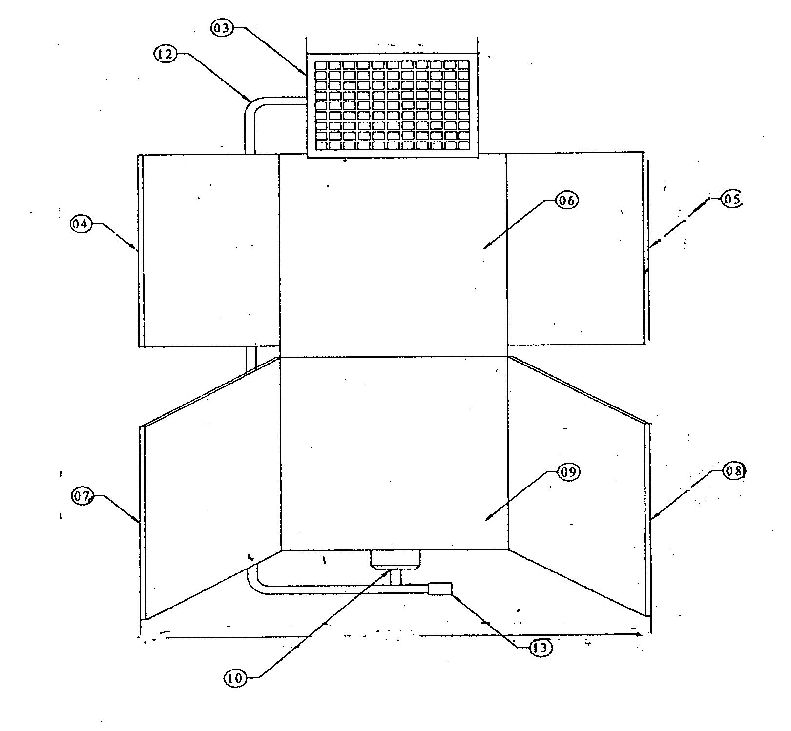
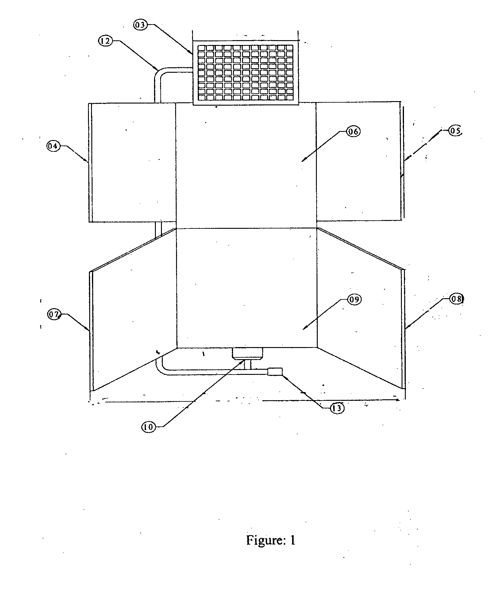
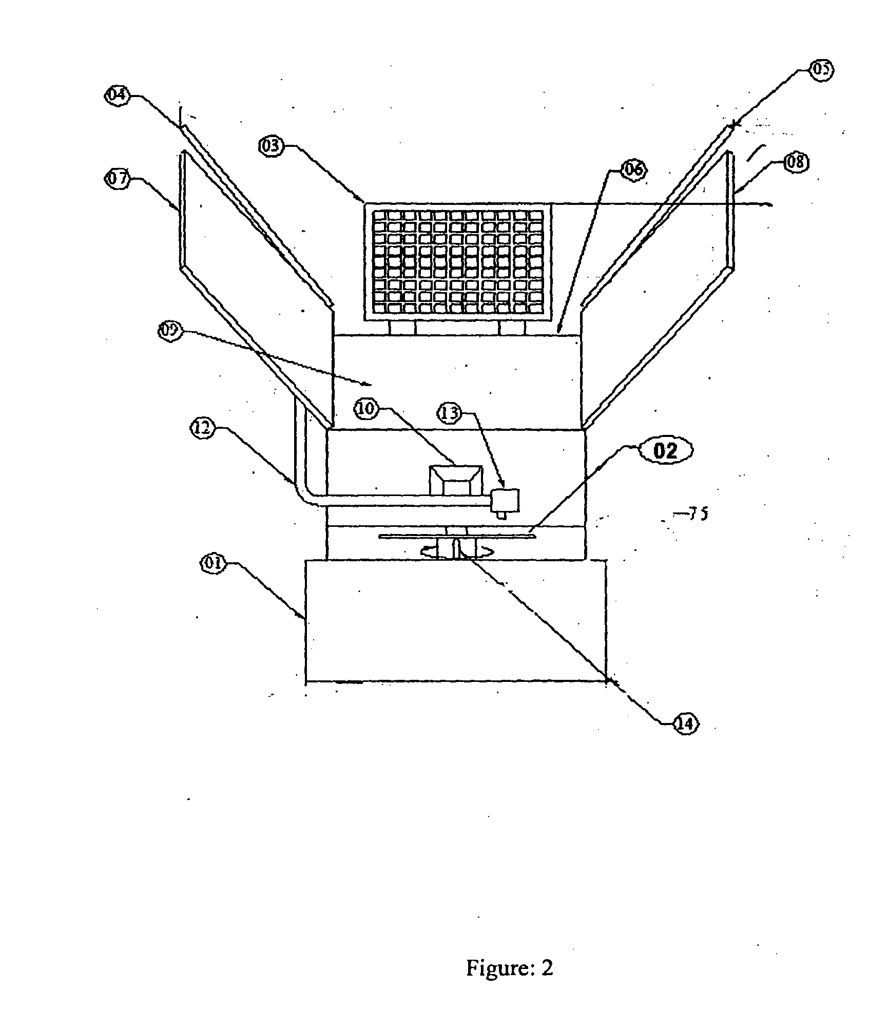
The present invention provides an improved solar dryer with improved. The dryer consists of a solar absorber / collector (9) and a drying chamber (6). One end of the collector is connected to a forced draft fan (10) and the other end connects the drying chamber. The drying chamber has a drawer in which the material to be dried is kept on a wire mesh. The dryer further has the provision for placing color indicative silica gel under the wire mesh when operated in recirculation mode. The other end of the drying chamber has an induced draft fan (11). Both the dc fans operate using a 10 watt photovoltaic panel (3). V-trough reflectors (4,5,7,8) made from anodized aluminum are fixed on the collector and optionally on the drying chamber. A tracking circuit is incorporated to auto-track the dryer. A locking mechanism (14) is also incorporated to help the unit withstand high wind load. The dryer further has the provision of programmable recirculation of the spent air from drying chamber once its humidity drops below a pre -set value which process helps to speed up the rate of drying.

Description

FIELD OF INVENTION[0001]The present invention relates to an improved solar dryer with enhanced efficiency of drying. Particularly the present invention relates to an improved solar dryer with enhanced solar radiation incident on the collector through the combination of alignment / tracking as appropriate use of reflectors. More particularly the present invention relates to attainment of a relatively more uniform drying air temperature throughout the period of insolation during a day by raising the overall efficiency of the dryer by raising the efficiency of the heat transfer from the absorber plate to the flowing air and also the efficiency of utilisation of the heated up air through recirculation as appropriate.BACKGROUND AND PRIOR ART[0002]Reference may be made to the article “Review of solar dryers for agricultural and marine products” published in Renewable and Sustainable Energy Reviews 14 (2010) 1-30 by A. Fudholi et al. This paper is a review of different types of solar dryers ...

Claims


Application Information

Patent Timeline
IPC IPC(8): F26B3/28
CPCF26B3/28F26B3/286F26B21/04F26B21/083Y02E10/44Y02E10/47F24S30/422F24S20/25F24S10/50F24S23/77Y02B40/18Y02E10/40
Inventor GHOSH, PUSHPITO KUMARMAITI, SUBARNAPATEL, PANKAJ ARVINDBHAIBHARADIA, JITENDRA NARSINHBHAICHAUHAN, SHOBHIT SINGHSANGHANI, MAHESH LAXMANBHAIPARMAR, PRADIP VINUBHAIESWARAN, KRUTHIKAAGRAVAT, PARASKUMAR VIVEKBABU
Owner COUNCIL OF SCI & IND RES
Learn More