Structure of a solar cell

Inactive Publication Date: 2011-03-03
NAT TAIWAN UNIV
View PDF13 Cites 0 Cited by
  • Summary
  • Abstract
  • Description
  • Claims
  • Application Information

AI Technical Summary

Benefits of technology

[0009]According to a first aspect of the invention, a structure of solar cell including a substrate, a base and a plurality of nanostructures is provided. The base is disposed on the substrate. The nanostructures are disposed on a surface of the base, so as to increase light absorption of the structure.
[0010]According to a second aspect of the invention, a structure of solar cell including a substrate, a first base, a second base and a plurality of nanostructures is provided. The first base is disposed on the substrate. The second base is disposed on a surface of the first base. The nanostructures are disposed on a surface of the second base, so as to increase light absorption of the structure.
[0011]According to a third aspect of the invention, a solar cell structure including a substrate and a base is provided. The base is disposed on the substrate, and a surface of the base has a plurality of nanostructures so as to increase light absorption of the structure.
[0012]According to a fourth aspect of the invention, a solar cell structure including a substrate, a first base and a second base is provided. The first base is disposed on the substrate. The second base is disposed on a surface of the first base, and a surface of the second base has a plurality of nanostructures so as to increase light absorption of the structure.

Problems solved by technology

However, the manufacturing process of such solar cell is costly and time consuming and not suitable for large-scale production for civil uses.
However, the cost increases significantly.

Method used


Image

  • Structure of a solar cell
  • Structure of a solar cell
  • Structure of a solar cell

Examples


first embodiment

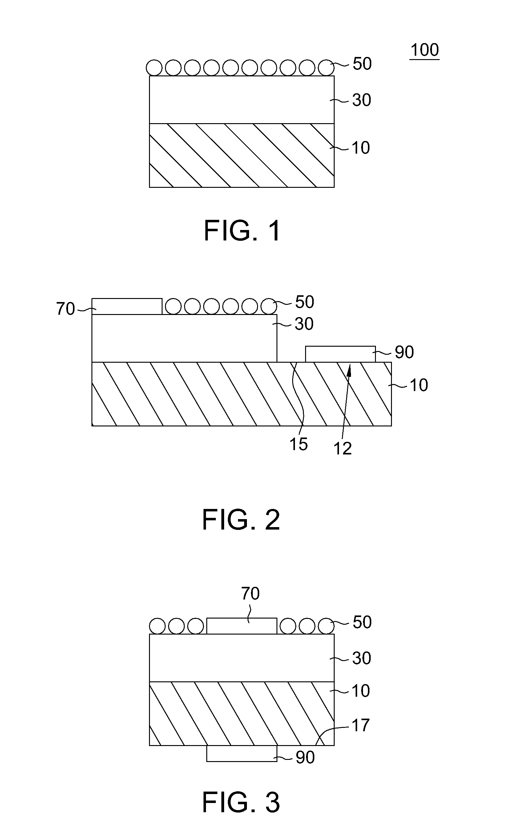
[0028]Referring to FIG. 1, a cross-sectional view of a solar cell according to a first embodiment of the invention is shown. The solar cell 100 includes a substrate 10, a base 30, and a plurality of nanostructures 50. The base 30 is disposed on the substrate 10. The nanostructures 50 such as nanoparticles are disposed on a surface of the base 30, or a surface of the base 30 has the nanostructures 50 to increase the light absorption of the entire solar cell 100.

[0029]In practical applications, electrodes can be disposed according to the structure of solar cell as shown in FIG. 1. FIG. 2 shows a cross-sectional view of an example of the structure of a solar cell of FIG. 1 having coplanar electrodes. In practical application, various implementations of disposition of electrodes on the solar cell 100 can be employed. According to an implementation shown in FIG. 2, a portion 12 of the substrate 10 extends over the base 30 for the disposition of the electrodes such as a first electrode 70...

second embodiment

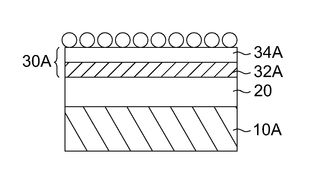
[0057]The solar cell 100A of the present embodiment differs from the solar cell 100 of the first embodiment in that the solar cell 100A includes a first base and a second base, which form a P—N junction, and that the substrate 10A is made from a transparent material, and the similarities are not repeated for the sake of brevity. To elaborate the solar cell of the present embodiment, a block diagram is disclosed below.

[0058]Referring to FIG. 10, a cross-sectional view of a solar cell according to a second embodiment is shown. The solar cell 100A has a substrate 10A, a first base 20, a second base 30A, and a plurality of nanostructures 50. The first base 20 is disposed on the substrate 10A. The second base 30A is disposed on the first base 20. The nanostructures 50 are disposed on a surface of the second base so as to increase the entire light absorption.

[0059]In the present embodiment, the substrate 10A can be made from a transparent material or a soft material. The transparent mater...


PUM


Abstract

A structure of a solar cell is provided. The structure of the solar cell includes a substrate, a base and a plurality of nanostructures. The base is disposed on the substrate. The nanostructures are disposed on a surface of the base, or a surface of the base includes the nanostructures, so as to increase light absorption of the structure.

Description

[0001]This application claims the benefit of Taiwan application Serial No. 98129308, filed Aug. 31, 2009, the subject matter of which is incorporated herein by reference.BACKGROUND OF THE INVENTION[0002]1. Field of the Invention[0003]The invention relates in general to a structure of solar cell, and more particularly to a structure of solar cell with high photoelectric conversion efficiency.[0004]2. Description of the Related Art[0005]Due to the energy crisis, the whole world is engaged in the pursuit of all sorts of alternative energies. Of the alternative energy sources with great development potential such as hydraulic power, wind power, solar power, terrestrial heat, sea water, temperature difference, waves, and tides, the solar power has become a mainstream of the new energies. According to estimation, the energy that the sun illuminated on the surface of the earth per year is one million times of the energy annually consumed by people on the earth. If 1% of the inexhaustible e...

Claims


Application Information

Patent Timeline
IPC IPC(8): H01L31/00
CPCH01L31/0236H01L31/0547Y02E10/52
Inventor HUANG, JIAN-JANGCHEN, CHENG-PINLIN, PEI-HSUAN
Owner NAT TAIWAN UNIV
Why Eureka
Try Eureka