Preparation method for stacked thin film cell and stacked thin film cell

A thin-film battery and stacking technology, which is applied in the manufacture of circuits, electrical components, and final products, can solve the problems of weakening the effect of improving TCO efficiency, increasing laser scribing insulation time and cost, and increasing the loss of battery effective area. To achieve the effect of improving light conversion efficiency, increasing loss, and reducing light absorption

Inactive Publication Date: 2015-04-22
ZHEJIANG ASTRONERGY
View PDF7 Cites 0 Cited by
  • Summary
  • Abstract
  • Description
  • Claims
  • Application Information

AI Technical Summary

Problems solved by technology

Compared with the battery process with an integrated series structure that can be realized after three lasers in the traditional process, this operation additionally increases the time and cost of laser scribing insulation
In addition, due to the four-pass laser scribing process, the loss of the effective area of ​​​​the battery is increased
This will weaken the efficiency improvement effect of TCO as an intermediate layer to a certain extent

Method used


Image

  • Preparation method for stacked thin film cell and stacked thin film cell
  • Preparation method for stacked thin film cell and stacked thin film cell
  • Preparation method for stacked thin film cell and stacked thin film cell

Examples


Embodiment Construction

[0032] The following disclosure provides many different embodiments or examples for implementing different structures of the present invention. To simplify the disclosure of the present invention, components and arrangements of specific examples are described below. Furthermore, the present invention may repeat reference numerals and / or letters in different instances. This repetition is for the purpose of simplicity and clarity and does not in itself indicate a relationship between the various embodiments and / or arrangements discussed. It should be noted that components illustrated in the figures are not necessarily drawn to scale. Descriptions of well-known components and processing techniques and processes are omitted herein to avoid unnecessarily limiting the present invention.

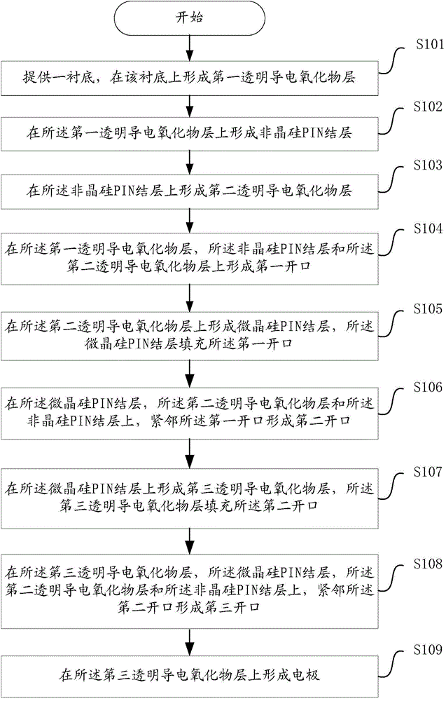
[0033] refer to figure 1 , figure 1 Shown is a schematic flow chart of a specific embodiment of a method for preparing a laminated thin film battery according to the present invention.

[0034...


PUM

PropertyMeasurementUnit
Thicknessaaaaaaaaaa

Abstract

The invention discloses a preparation method for a stacked thin film cell and the stacked thin film cell. A middle layer between two sub-cell layers in the stacked thin film cell is made of a transparent conductive oxide (TCO) and the whole stacked thin film cell is of an integrated series structure. According to the preparation method, the structure of the stacked thin film cell can be acquired through three times of laser operation. The TCO middle layer adopted in the stacked thin film cell has the electrical conductivity higher than a tunneling junction so that the series resistance between the two cell layers can be effectively reduced; the TCO is used as the middle layer so that the light reflection of the middle layer can be improved and the light use rate of the top cell can be increased when light absorption is reduced. In addition, extra electricity leakage and effective area loss of the cell can not be increased and cell efficiency is higher.

Description

technical field [0001] The invention relates to the technical field of thin film solar cells, in particular to a preparation method of a stacked thin film battery and the stacked thin film battery. Background technique [0002] In the field of photovoltaics, the current conventional stacked thin film cells are basically stacked thin film cell structures connected by tunnel junctions, for example: the cell structure disclosed in the patent US2006 / 0043517 (refer to the drawings in the patent publication). Since the intrinsic silicon or silicon compound is required to form a tunnel junction between amorphous silicon and microcrystalline silicon, this will absorb light, so that the light reaching microcrystalline silicon will be correspondingly reduced, which will cause microcrystalline silicon cells to The utilization rate of light is correspondingly reduced, which ultimately reduces the conversion efficiency of the microcrystalline silicon layer cell. In addition, in the abov...

Claims


Application Information

Patent Timeline
IPC IPC(8): H01L31/20
CPCH01L31/03685H01L31/03762H01L31/1824H01L31/202Y02P70/50
Inventor 李旺刘石勇牛新伟王仕鹏黄海燕陆川
Owner ZHEJIANG ASTRONERGY
Why Eureka
Try Eureka