Method of estimating direction of arrival and apparatus thereof

a technology of direction and direction, applied in the direction of direction finders, multi-channel direction-finding systems using radio waves, radio wave direction/deviation determination systems, etc., can solve the problems of inability to achieve sufficient estimation precision, difficulty in real-time processing with music or espri

Inactive Publication Date: 2011-03-03
FUJITSU LTD
View PDF6 Cites 40 Cited by
  • Summary
  • Abstract
  • Description
  • Claims
  • Application Information

AI Technical Summary

Problems solved by technology

However, when it is assumed that a central processing unit (CPU) of several tens of mega hertz (MHz) is to be used, it is difficult to perform real-time processing with the MUSIC or the ESPRIT because the computation load for eigenvalue decomposition, which is the main computation process required in the SSM, is large.
On the other hand, with the propagator method or an orthonormal propagator method, which is an improved version of the propagator method, real-time processing can be performed because the main computation process is merely calculation of inverse matrices, but sufficient estimation precision cannot be achieved.

Method used


Image

  • Method of estimating direction of arrival and apparatus thereof
  • Method of estimating direction of arrival and apparatus thereof
  • Method of estimating direction of arrival and apparatus thereof

Examples


first embodiment

Operation and Advantage of First Embodiment

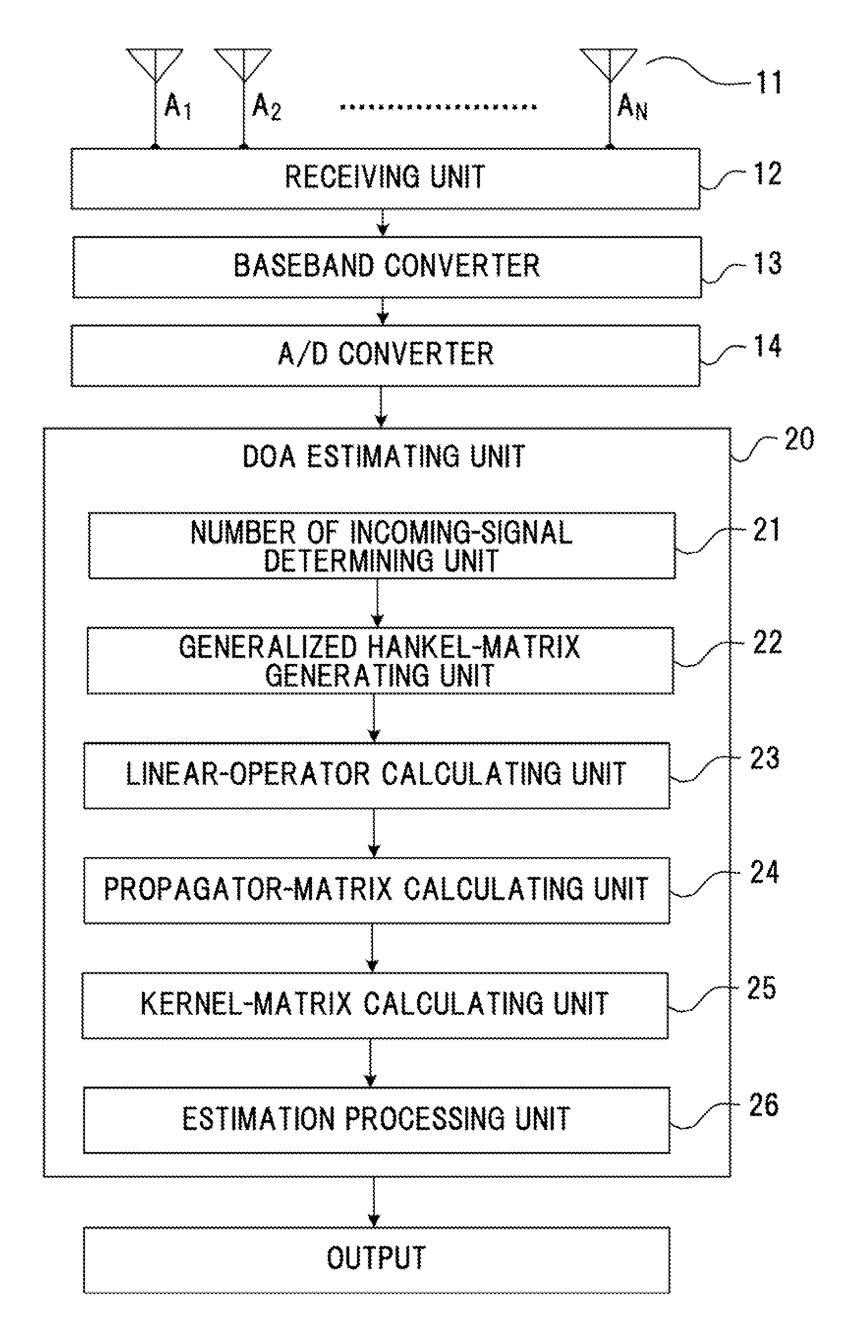
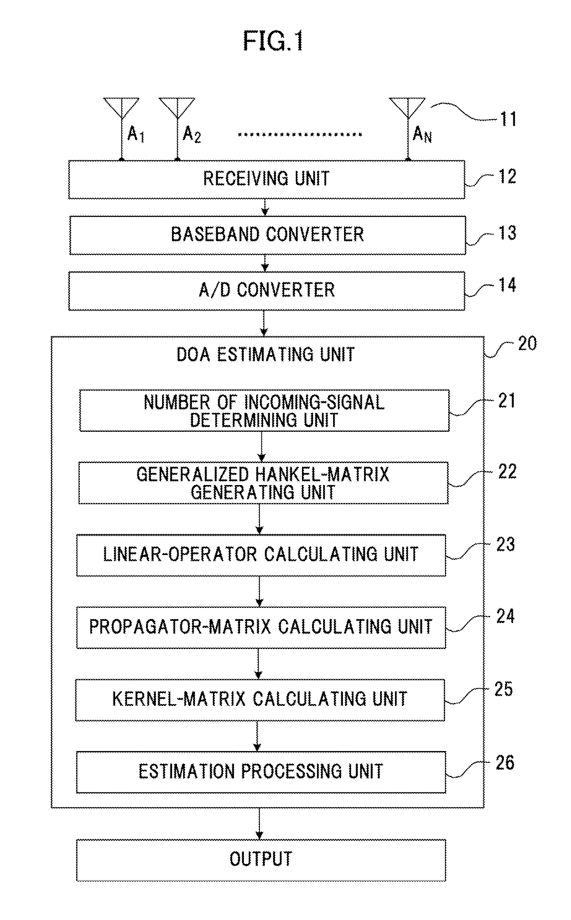
[0067]With the DOA estimating apparatus according to the first embodiment, baseband signals are generated from the signals received at N sensor devices in the sensor array 11, and, then, digital signals are generated (receiving unit 12, baseband converter 13, and A / D converter 14). Subsequently, the generalized Hankel-matrix generating unit 22 of the DOA estimating unit 20 generates a generalized Hankel matrix R from a correlation vector of combined-echo-signal vectors v(t) containing the digital signals as elements (generalized Hankel-matrix generating unit 22).

[0068]The linear-operator calculating unit 23 and the propagator-matrix calculating unit 24 perform linear computation using submatrices R1 and R2 of the generated generalized Hankel matrix R to generate a linear operator Γ and a propagator matrix Π or an orthogonal propagator matrix Π′. By using the generated matrices, the kernel-matrix calculating unit 25 generates a kernel matrix...

second embodiment

[0077]FIG. 3 is a block diagram illustrating the configuration of a DOA estimating apparatus according to a second embodiment. As illustrated in FIG. 3, the DOA estimating apparatus according to the second embodiment has the same configuration as that of the first embodiment and, in addition, includes a scaling-matrix calculating unit 31. Structures of the DOA estimating apparatus according to the second embodiment that differ from those of the first embodiment will be described below.

[0078]The number of incoming-signal determining unit 21 according to the second embodiment sets the number of incoming signals M to the maximum number for which angle estimation can be performed by the sensor array 11. In such a case, the number of incoming signals M is set to, for example, the maximum natural number smaller than or equal to (N−1) / 2. The number of incoming-signal determining unit 21 may save in a memory in advance, the number of incoming signals M, which is determined as described abov...


PUM


Abstract

A method includes generating a correlation vector of baseband-signal vectors based upon signals received from a plurality of sensor devices, generating a generalized Hankel matrix R representing a covariance matrix to which a spatial averaging is applied based upon the correlation vector, generating a kernel matrix Ω1, which is a projection matrix onto noise subspace, by performing linear operation using submatrices R1 and R2 of the generalized Hankel matrix R, generating a kernel matrix Ω2, which is orthogonal with the kernel matrix Ω1, and estimating a direction of arrival of a signal based upon the kernel matrices Ω1 and Ω2.

Description

CROSS-REFERENCE TO RELATED APPLICATIONS[0001]This application is based upon and claims the benefit of priority of the prior Japanese Patent Application No. 2009-201624, filed on Sep. 1, 2009, the entire contents of which are incorporated herein by reference.FIELD[0002]The embodiments discussed herein relate to a technique for estimating a direction of arrival (DOA) of an incoming signal using a sensor array.BACKGROUND[0003]Typical methods of DOA estimation of a signal using a sensor array include digital beamforming (DBF), a subspace method (SSM), and maximum likelihood (ML) estimation. The DBF method includes a Capon method and linear prediction. The SSM includes multiple signal classification (MUSIC), estimation of signal parameters via rotation invariance techniques (ESPRIT), and a propagator method. The ML estimation includes a method of direction estimation (MODE).[0004]In these methods, the estimation precision and the computation load increases in the following order: DBF<...

Claims


Application Information

Patent Timeline
Patent Type & Authority Applications(United States)
IPC IPC(8): G01S3/16
CPCG01S3/74G01S3/46
Inventor SHIRAKAWA, KAZUO
Owner FUJITSU LTD
Why Eureka
Try Eureka