Presentation of Objects in Stereoscopic 3D Displays

a technology of 3d display and object, applied in the direction of instrumentation, user interface execution, static indicating device, etc., can solve the problems of limited practical usefulness, limited 3d effect on conventional 2d display, and lack of practical use of 3d guis of this type outside of particular specialised applications

Inactive Publication Date: 2011-03-03
PICSEL INT LIMITED A MALTA
View PDF7 Cites 122 Cited by
  • Summary
  • Abstract
  • Description
  • Claims
  • Application Information

AI Technical Summary

Benefits of technology

[0011]Broadly speaking, given a set of graphical objects that are to be displayed, subsets of those objects may be defined to which a given PS3D effect is to be applied. Any object to which such an effect is to be applied will be displayed by rendering, via any suitable 3D display technology, a pair of laterally displaced copies (left-eye and right-eye copies) of the object in respective views of the overall display content that are presented to the left and right eyes by means of the 3D display technology.
[0012]For the purposes of the present description, content to be displayed according to the invention may comprise a plurality of “display items” that would “normally” be displayed in 2D, without any 3D effects. That is, any display item to which a PS3D effect is applied would, if displayed in the absence of such an effect, have an “unmodified 2D screen location”. In general terms, the application of a PS3D effect to a display item causes left-eye and right-eye copies of the display item to be displayed at respective screen locations that are laterally offset from one another relative to the unmodified 2D screen location.
[0013]The display is generated by a rendering system of a computer or other data processing system, which include mobile telephones and other portable devices. As used herein, “display item” refers to items as they appear on a display screen and the term encompasses any subset of screen display content to which a PS3D

Problems solved by technology

It is also known to obtain a limited 3D effect on a conventional 2D display by visibly flipping the display between left and right images of a stereoscopic image pair.
This provides an impression of the 3

Method used


Image

  • Presentation of Objects in Stereoscopic 3D Displays
  • Presentation of Objects in Stereoscopic 3D Displays
  • Presentation of Objects in Stereoscopic 3D Displays

Examples


Embodiment Construction

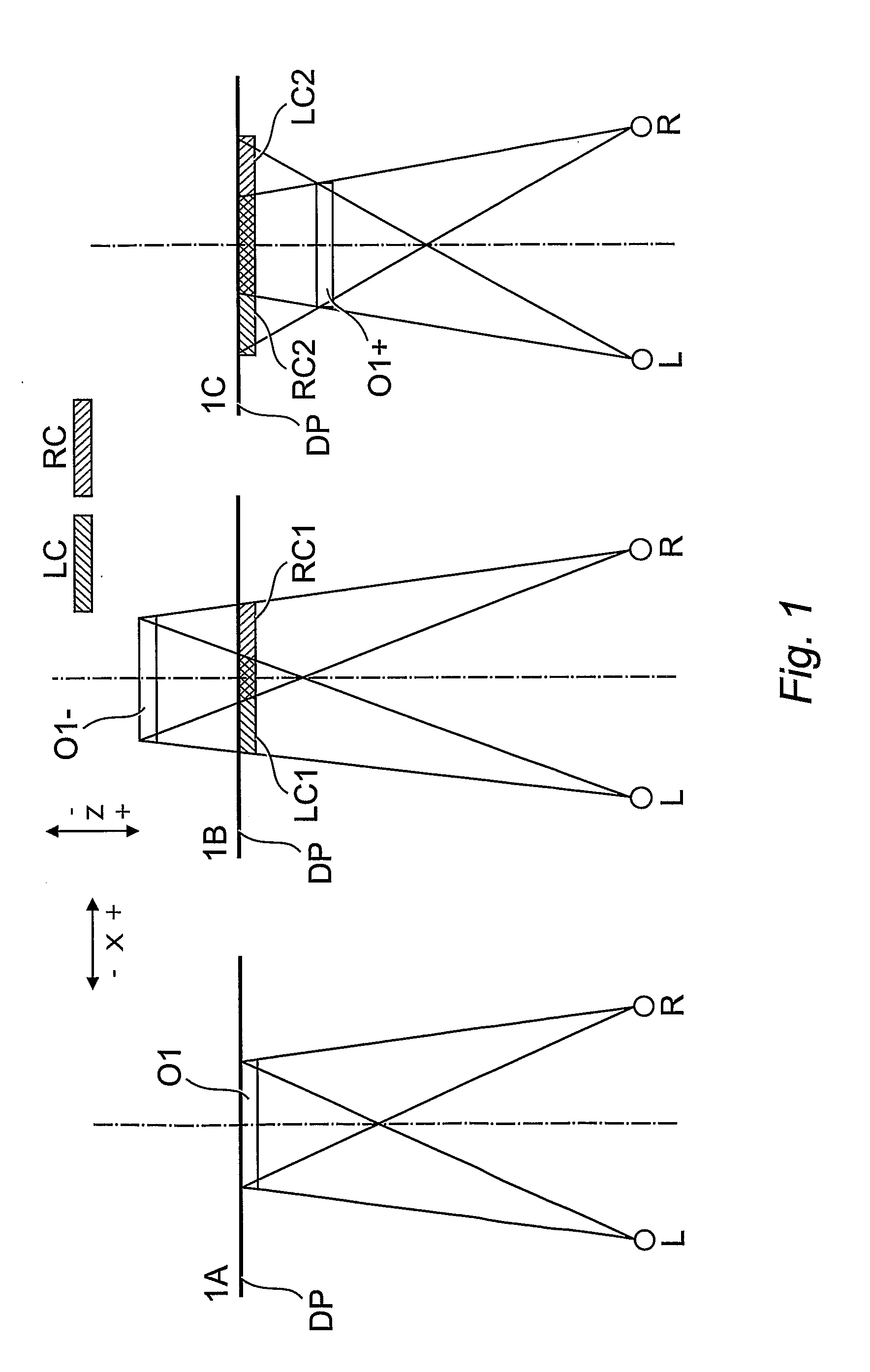
[0059]Referring now to the drawings, FIG. 1 illustrates the optical principles of the PS3D effect that forms the basis for the preferred embodiments of the invention. In FIG. 1, directions x and z are indicated, L and R are the left and right eyes of a viewer, DP is the plane of the screen of a visual display unit (display plane), O1 is a display item displayed on the screen, and LC and RC are left- and right-eye copies (“PS3D copies”) of the item O1 created for the purpose of creating a PS3D effect. The item O1 is a 2D (x / y) graphical object and is shown having a thickness in the z-direction for clarity of illustration only.

[0060]Note: The use of “positive” and “negative” in relation to the x- and y-directions herein follows the convention for co-ordinate systems in computer displays, where the origin is at the top left of the display screen.

[0061]Thus, the positive x-direction is from left to right and the positive y-direction is from top to bottom. For the z-direction, as used he...


PUM


Abstract

A data processing system includes a rendering system adapted to process data objects to render display frames for presentation via a visual display screen. The display frames include 2D display items corresponding to the data objects, each display item having a 2D screen location within the display frame defined by reference to an X/Y display plane. The rendering system renders stereoscopic 3D views of display frames by rendering left- and right-eye views of the display frames. The left- and right-eye views of the display frames are rendered by processing the data objects corresponding to the 2D display items such that respective left- and right-eye copies of the 2D display items are included in the left- and right-eye views. A set of 3D effects rules is provided that specify relationships between stereoscopic 3D effects and parameters associated with the data objects corresponding to the 2D display items. The stereoscopic 3D effects include lateral offsets in the X-direction of the X/Y display plane to be applied when rendering left- and right-eye copies of display items at respective screen locations, such that selected 2D display items may be perceived by a viewer as being displaced along a Z-axis perpendicular to said X/Y plane. Corresponding computer-implemented methods and computer program products are also included.

Description

FIELD OF THE INVENTION[0001]The invention relates to the visual display of information using stereoscopic, three-dimensional (3D) visual display technology. More particularly, the invention is concerned with methods and systems whereby data representing 2D information that is to be displayed by means of a stereoscopic visual display unit is processed such that selected elements of the information displayed will be perceived by a viewer as being displaced in a direction perpendicular (z-direction) to the plane of the screen (x / y plane) of the visual display unit.BACKGROUND TO THE INVENTION[0002]A variety of 3D visual display technologies are known in the art, all of which (apart from volumetric displays that form a visual representation of an object in three physical dimensions, as opposed to the planar image of traditional screens) are based on the well known principles of stereoscopy whereby slightly different 2D views of a 3D subject are presented to each of the viewer's eyes, the...

Claims


Application Information

Patent Timeline
IPC IPC(8): G06T15/00
CPCG06F9/4443G06T15/00G06T2200/24G09G2340/14H04N13/026G09G3/003G09G5/14H04N13/004H04N13/156H04N13/261G06F9/451
Inventor ALYSHEV, DENIS VLADIMIROVICHMCGINLEY, JAMESMAJID, ANWAR
Owner PICSEL INT LIMITED A MALTA
Why Eureka
Try Eureka